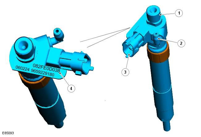
| Pos. | spare part no | Name |
| 1 | - | High pressure fuel supply from the fuel manifold |
| 2 | - | Low pressure fuel return to filter |
| 3 | - | Electrical connection on ECM |
| 4 | - | 10 digit injector code |
These four fuel injectors are of the piezoelectric type, with 7 orifices in the atomizer. The nozzles are centrally located in the combustion chambers of the cylinder head and serve to spray fuel directly onto the toroidal piston crown.
Technical details
| Operating parameter | Meaning |
| Supply voltage 110 - 150 V | 230 - 1,600 bar |
| Resistance | 180 kΩ at 20°C |
| Minimum charge time | 100 µs |
| Minimum unloading time | 100 µs |
| Nozzle diameter | 143 µm |
| Maximum performance | 11 cm3 /sec |
At manufacture, each injector is tested to measure the actual amount of fuel injected against a reference value for simulated conditions. Tests are used to classify injectors, the difference in injection analysis results is converted into a 10-digit alphanumeric code that is stamped on the injector body.
The 10-digit codes are stored in the ECM along with the corresponding cylinder numbers for each injector and software tables with engine specifications. The ECM recognizes each injector's 10-digit code and adapts each injector's operation to provide similar injection pressures and fuel delivery rates for current operating conditions, according to software-based characterization tables.
The nozzle body contains a set of piezoelectric crystals mounted above the control piston. The piezocrystals are activated by supply voltage from the ECM. The control piston is separated by a hydraulic chamber which acts to activate the needle valve through the domed piston and control channels. The hydraulic chamber compensates for temperature changes in the nozzle and also allows the nozzle to operate with a constant response time, even after numerous work cycles.
The hydraulic chamber eliminates the need for this type of nozzle to have moving parts in contact. In other types of injectors, these contacting parts will wear out, increasing injector response time and subsequently affecting engine performance and emissions.
On the vehicle, the hydraulic chamber is supported by a 10 bar check valve located at the injector bypass connection.
Due to the use of 3rd generation Bosch technology and the hydraulic chamber, the injectors will operate with approximately instantaneous response time to ECM commands. This provides a finer atomization of the injected fuel and allows the ECM to precisely control the injector activation period. Under certain operating conditions, each injector is capable of delivering a sequence of up to 5 injections per injection cycle. The injection cycle sequence of 5 separate events is as follows:
- Two pilot injections up to 3,200 rpm
- Single control injection at up to 4,500 rpm
- One main injection above 4,500 rpm
- Two subsequent injections during the DPF regeneration phase (no load)
The pre-injection phase occurs before the main charge of fuel is injected to provide a stable flame front and create a gradual increase in cylinder pressure. The pre-injection phase reduces the delay between fuel injection and the onset of combustion, allowing the remaining amount of fuel to be injected when combustion occurs. This injection principle increases power, improves NVH performance and reduces exhaust emissions.
On models equipped with a diesel particulate filter, the high pressure fuel system also provides after injection of fuel into the combustion chambers. During the regeneration phase of the DPF, the ECM allows fuel to be injected after the combustion stroke and at the beginning of the exhaust stroke. This post-injection process burns the fuel in the exhaust system and generates the high exhaust gas temperature required for DPF regeneration.
For more information see the chapter: Electronic Engine Controls - 2.2L Diesel (303-14 Electronic Engine Controls - 2.2L Diesel, Description and function) / Exhaust system (309-00B Exhaust system - 2.2L Duratorq - Td4, Description and operation).
Nozzle Maintenance Information
CAUTION: This type of nozzle contains a hydraulic chamber. It is important to handle the nozzles correctly to prevent the hydraulic chamber from emptying. The nozzle should be plugged and maintained in a vertical position. The nozzle should not be laid on its side or shaken.
Do not attempt to remove carbon deposits from the diesel injector nozzle.
The nozzle is supplied as a single unit. The proprietary nozzle should not be disassembled.
NOTE: TD4 engine cylinders are numbered from the rear of the engine (from the gearbox side). Therefore, cylinder #1 and injector #1 are located at the rear of the engine.
Each time the injector is removed from the cylinder head, install a new copper washer and discard the old washer. The nozzle centering ring can be reused.
If an injector is removed, it should be returned to the cylinder from which it was removed during installation, in which case it does not need to be reprogrammed into the ECM.
If an injector is being replaced, use the Land Rover approved diagnostic system to program the 10-digit code for the new injector and the corresponding cylinder number into the ECM.
If the ECM is being replaced, use the Land Rover approved diagnostic system to program the 10-digit codes for all four injectors and the corresponding cylinder numbers into the new ECM.
Comments on this article