Contents: Dismantling ⇩ Assembly ⇩
Before disconnecting the battery, make sure that all requirements and conditions contained in the section on disconnecting the battery are met.
GENERAL INFORMATION, Precautions when working with electrical equipment.
Dismantling
1. Disconnect the negative battery terminal.
WARNING: Fuel vapors are highly flammable and toxic and explosive in confined spaces. Always have a foam, carbon dioxide (CO), gas or powder fire extinguisher on hand when working with fuel.
2. Remove the exhaust gas recirculation (EGR) heat exchanger.
EMISSION CONTROL SYSTEMS - Td6, REPAIR WORK, Exhaust Gas Recirculation (EGR) Cooler.
3. Remove the intake manifold gaskets.
EXHAUST MANIFOLD AND EXHAUST SYSTEM: Td6 engine, REPAIR WORK, Intake manifold gaskets.
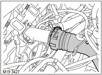
4. Loosen the clamp and disconnect the upper hose from the cooling system pipe.
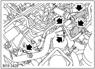
5. Loosen the clamps and disconnect the heater and transmission oil cooling heat exchanger hoses from the distribution pipe.
6. Release the fuel pipe from the fastening to the distribution pipe of the cooling system.
7. Unscrew the 2 bolts securing the cooling system distribution pipe.
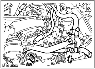
8. Loosen the clamp and disconnect the vacuum hose from the vacuum pump.
CAUTION: Always plug the fittings and holes to protect the system from dirt.
9. Loosen the clamp and disconnect the expansion tank hose from the cooling system distribution pipe.
10. Loosen the clamp and disconnect the distribution tube from the thermostat housing.
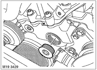
11. Unscrew the plug of the mounting window in the timing belt cover and dispose of the gasket.
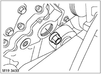
12. Unscrew the fuel pump drive sprocket fastening nut.
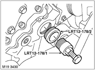
13. Screw the LRT-12-178/2 mandrel into the timing belt cover.
14. Install the LRT-12-178/1 puller on the fuel pump sprocket and, tightening the central bolt of the puller, remove the sprocket.
CAUTION: Do not remove the puller from the sprocket until the fuel pump is installed.
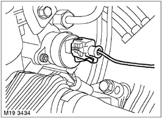
15. Disconnect the connector from the fuel pump. ATTENTION: It is strictly forbidden to disconnect the connector from the fuel pump when the ignition is on.
16. Place a rag under the fuel pump to collect any leaking fuel.
CAUTION: Avoid allowing oil or hydraulic fluid to come into contact with the generator.
17. Cover the generator to prevent it from coming into contact with the working fluid.
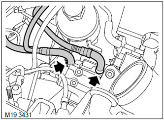
18. Unscrew the 2 clamps and disconnect the fuel hoses from the pump.
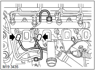
19. Loosen the 2 nuts and remove the high-pressure fuel pipe. Remove the pipe support sleeve.
CAUTION: Always plug the fittings and holes to protect the system from dirt.
20. Disconnect the caps from the glow plugs of the 1st and 2nd cylinders and move them away from the fuel pump.
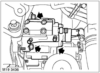
21. Unscrew the 3 nuts, release and remove the fuel pump. Discard the gasket.
Assembly
1. Wipe the fuel pump and mating surfaces.
2. Install a new fuel pump gasket.
3. Install the fuel pump in place and tighten the mounting nuts. Tightening torque 24 N·m.
4. Place the caps on the glow plugs.
5. Wipe the high pressure fittings.
6. Install the high-pressure fuel pipe and support sleeve, tighten the nut on the pipe. Tightening torque 20 N·m.
7. Connect the fuel hoses to the pump and tighten the clamps.
8. Connect the connector to the pump.
9. Remove the LRT-12-178/2 mandrel and the LRT-12-178/1 puller.
10. Screw on the fuel pump sprocket mounting nut and tighten it. Tightening torque 65 N·m.
11. Wipe the mounting hole plug.
12. Replace the plug and tighten it. Tightening torque 30 Nm.
13. Wipe the thermostat housing and the cooling system distribution pipe.
14. Install the coolant distribution pipe, screw in the bolts and tighten them to a torque of 10 N·m.
15. Connect the hoses to the distribution pipe and secure them with a clamp.
16. Connect the upper hose to the branch pipe and secure with a clamp.
17. Secure the fuel line to the clamp on the cooling system distribution line.
18. Connect the hose to the vacuum pump and secure it with a clamp.
19. Install the intake manifold gaskets.
EXHAUST MANIFOLD AND EXHAUST SYSTEM: Td6 engine, REPAIR WORK, Intake manifold gaskets.
20. Install the exhaust gas recirculation (EGR) heat exchanger.
EMISSION CONTROL SYSTEMS - Td6, REPAIR WORK, Exhaust Gas Recirculation (EGR) Cooler.
21. Connect the negative battery terminal.
Comments on this article