


Contents: Arrangement of elements ⇩ Operating principles ⇩ Barometric pressure sensor ⇩ Turbocharger lubrication ⇩ Charge air cooler ⇩
Arrangement of elements
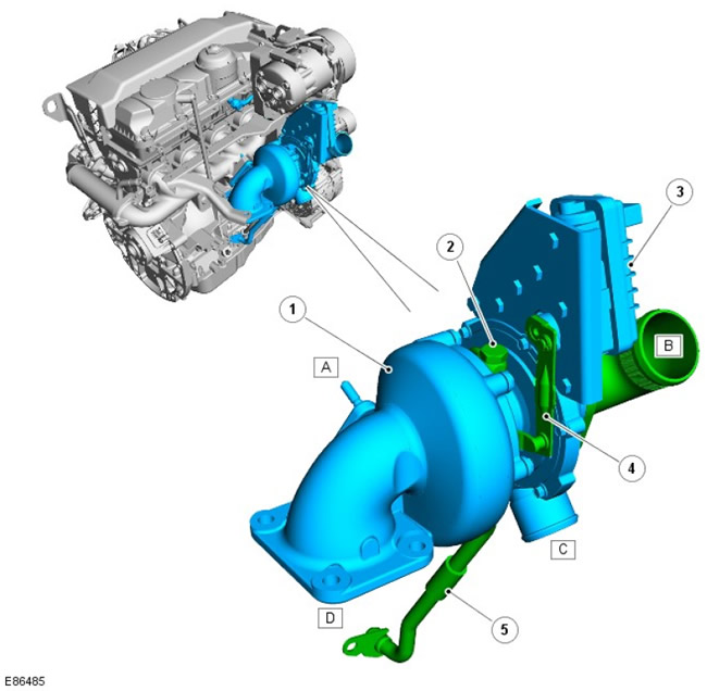
| Pos. | Spare No | Name |
| д | parts | Exhaust manifold connection |
| B | - | Air intake connection |
| C | - | Intercooler connection (intercooler of charge air) |
| D | - | Exhaust pipe connection |
| 1 | - | Turbocharger housing |
| 2 | - | Oil supply |
| 3 | - | Drive motor |
| 4 | - | Drive lever |
| 5 | - | Return oil line |
A turbocharger with a variable nozzle device, installed on the exhaust manifold, allows varying the flow of exhaust gases of the turbine depending on the engine operating mode. This leads to an increase in the power realized on the turbine, especially in the region of low crankshaft rotation frequencies, and to an increase in boost pressure. As the engine speed increases, the device blades gradually move to an open position, maintaining a balance of the power realized on the wheel in accordance with the requirements of the speed and load modes. Compared with traditional TCRS, which use bypass valves, a TCRS with a variable nozzle device has a higher efficiency.
Advantages:
- High engine torque at high and low rpm
- Continuous and smooth regulation at all engine speeds
- No need for a boost pressure regulator, better use of exhaust gas energy, lower back pressure with the same compressor operation
- Low thermal and mechanical load improves engine energy performance
- Lower exhaust toxicity
- Optimization of specific fuel consumption throughout the entire engine operating speed range
[Details can be found on the website: LRman.ru]
The drive shaft is driven by a DC electric motor of the rotation drive. The drive shaft is connected to the blades by a drive lever. The movement of the lever causes the blades of the device to move. The rotation of the drive shaft forms a feedback signal, which carries information about the angular position of the blades. This information is transmitted to the engine control unit (ECM).
The turbocharger provides fail-safe operation. If a control failure occurs, the device's blades default to the fully open position to reduce boost to a minimum. The engine control unit monitors stepper motor malfunctions and generates error codes.
Operating principles
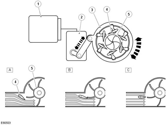
| Pos. | Spare No | Name |
| A | parts | Low engine crankshaft speed |
| B | - | Average engine crankshaft speed |
| C | - | Maximum engine crankshaft speed |
| 1 | - | ECM |
| 2 | - | Drive motor |
| 3 | - | Adjusting ring |
| 4 | - | Blades of the device |
| 5 | - | Turbine wheel |
A - Low crankshaft speed
At low engine speeds, the exhaust gas volume is small, so the vanes move toward the closed position to reduce the turbine intake cross-sectional area. This reduction causes an increase in the gas feed rate to the impeller, thereby increasing the wheel speed and boost pressure.
B - Average crankshaft speed
As the engine crankshaft speed increases, the exhaust gas volume also increases. The blades move toward the open position to increase the turbine inlet cross-sectional area and maintain gas velocity.
C - Maximum crankshaft speed
At maximum engine speed, the blades are almost fully open, maintaining the velocity of the gas entering the turbine wheel.
Barometric pressure sensor
When the vehicle is operated at high altitude, the ambient pressure decreases, forcing the compressor wheel to do less work to produce the same boost pressure. To prevent the turbine from over-speeding under these conditions, a barometric pressure sensor located in the ECM protects the turbocharger by opening the vanes further to reduce the speed of the impeller. This is called the turbocharger's altitude range.
Turbocharger lubrication
During rapid acceleration or deceleration, a smooth flow of clean oil is essential for the turbocharger. The oil supplied by the engine lubrication system provides lubrication to the turbocharger shaft and bearings, and also acts as a coolant for the turbocharger central housing.
To maintain the expected service life of the turbocharger, it is important that oil can flow freely through the turbocharger and return to the engine crankcase without obstruction. Therefore, it is essential to top up with the recommended amount of engine oil of the recommended quality at regular service intervals.
Charge air cooler
The charge air cooler is used to increase the density of the air supplied from the turbocharger to the intake manifold.
When the charge air is compressed in the turbocharger, the air temperature rises. This heat release reduces the density of the air, resulting in less oxygen entering the cylinders, which reduces engine power. To compensate for this, the air passes through a charge air cooler before entering the engine. The temperature is reduced by releasing heat into the atmosphere.
Intake air cooling also helps reduce exhaust emissions by limiting the production of nitrogen oxides (NOx).
Comments on this article