Contents: Chassis ⇩ Body ⇩ Chassis frame alignment ⇩ Chassis 90 ⇩ Dimensions for engine installation -…⇩ Chassis 110 ⇩ Chassis 130 ⇩ Clearance and Tolerance Information ⇩
Chassis
The chassis on all Defender variants is made from box-section sections and has a frame structure. The structural material is 2 mm thick steel, treated with zinc phosphate and having a cathodic coating. The rear cross member is treated with mastic.
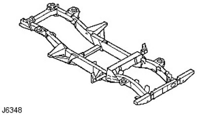
The outriggers and inclined brackets are welded to the chassis support suspension and axle elements and are also used as support points for the body. A removable box-section crossmember is installed between the two chassis side members, which makes it easier to remove the gearbox and transfer case.
In the event of chassis damage, there is a wide range of components including body outriggers, cross members and trailing arm support brackets. ALWAYS use genuine parts that are covered by warranty and that are to the original equipment specification and fitted to Land Rover's welding standard BS 5135.
Body
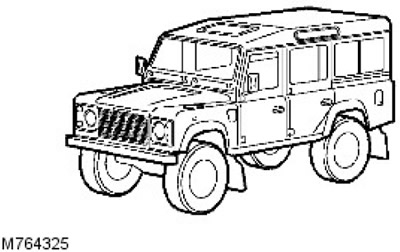
All body panels, with the exception of the front panel bulkhead, are made of aluminum alloy. Galvanized steel is used for the front wheel arches to provide optimum protection. Most panels are also treated with zinc phosphate and have a cathodic coating with polyester putty. The panels are bolted to the welded chassis.
Chassis frame alignment
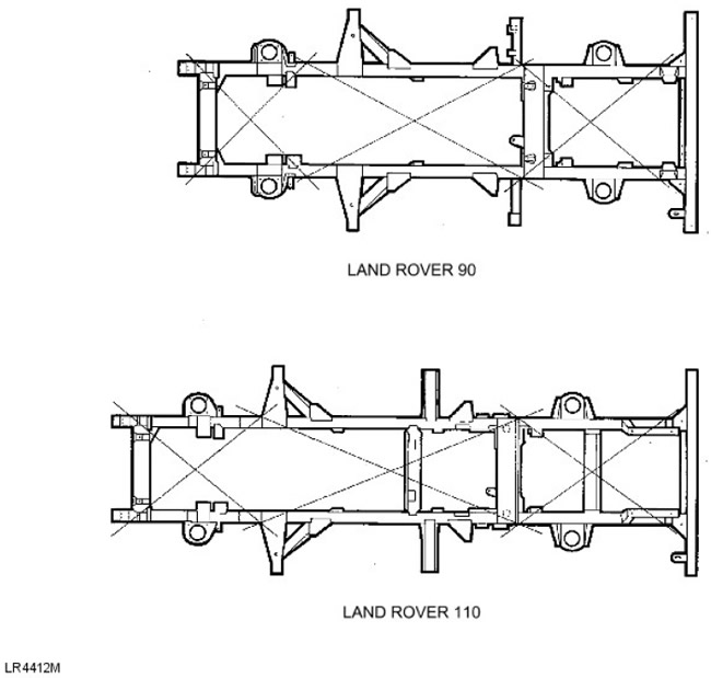
After assembling the vehicle, you can check the chassis perpendicularity by proceeding as follows:
- 1. Place the vehicle on a level, horizontal surface.
- 2. Mark the measurement points at approximately the locations shown in LR4412M. Ensure that the markings are symmetrically located on each side of the chassis frame.
- 3. Fix the plumb line opposite each of the measurement points in turn and make a mark on the floor directly under the plumb line.
- 4. Move the vehicle and measure diagonally between the marks made on the floor. If the chassis geometry is not disturbed, the length of the diagonals between the corresponding measurement points should be within 9.50 mm.
- 5. The dimensions of the chassis frame can be checked when the upper structure of the vehicle is removed, according to the relevant drawing and symbols.
Chassis 90
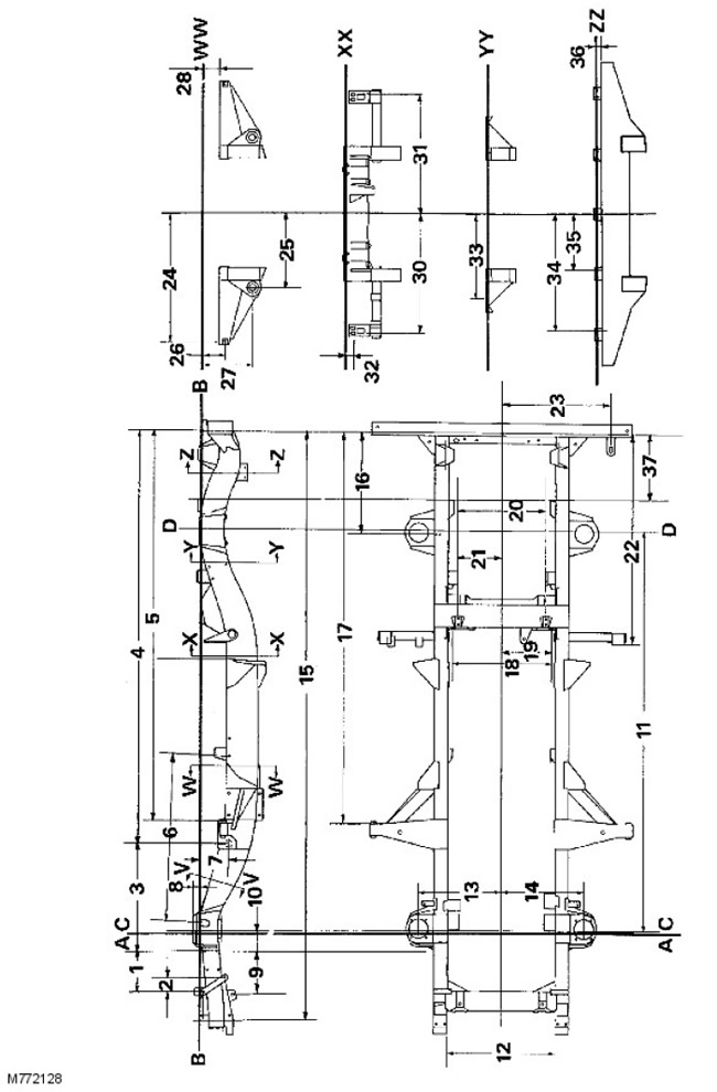
Chassis control dimensions
| No./letter | Size |
| A | Front dimensions |
| B | Chassis dimensions |
| C | Front axle centerline |
| D | Rear axle centerline |
| 1 | 239.0 - 236.5 mm |
| 2. | 82.0 - 79.5 mm |
| 3. | 633 mm |
| 4. | 2420.6 - 2418.6 mm |
| 5. | 2306.4 - 2305.4 mm |
| 6. | 981.2 - 978.7 mm |
| 7. | 182.7 mm |
| 8. | 41.5 - 37.0 mm |
| 9. | 252 - 250 mm |
| 10. | 110 mm |
| 11. | 2360 mm - Wheelbase |
| 12. | 636 - 634 mm |
| 13. | 488 - 482 mm |
| 14. | 488 - 482 mm |
| 15. | 3431.1 - 3426.1 mm |
| 16. | 588.3 - 586.3 mm |
| 17. | 2313.8 - 2311.8 mm |
| 18. | 590.5 mm |
| 19. | 295.25 mm |
| 20. | 519.30 - 517.30 mm |
| 21. | 259.80 - 258.50 mm |
| 22. | 1242.6 - 1240.6 mm |
| 23. | 642.5 - 639.5 mm |
| 24. | 750.9 mm |
| 25. | 439.5 - 436.5 mm |
| 26. | 136.5 mm |
| 27. | 299.5 - 295.5 mm |
| 28. | 103 - 100 mm |
| 29. | 131.5 - 126.5 mm |
| 30. | 705.5 - 704.5 mm |
| 31. | 705.5 - 704.5 mm |
| 32. | 42.2 - 40.2 mm |
| 33. | 491 - 486 mm |
| 34. | 594.2 - 593.4 mm |
| 35. | 283.0 - 282.2 mm |
| 36. | 32.25 - 31.25 mm |
| 37. | 397 - 395 mm |
Dimensions for engine installation - VV section
NOTE: Engine support bracket dimensions apply to all models.
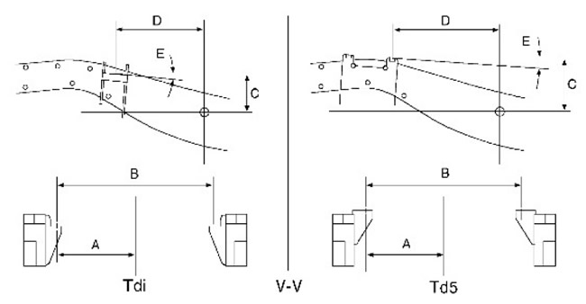
Dimensions for Tdi
| Size | Meaning |
| A | 276.5 mm |
| B | 553 mm |
| C | 127.9 mm |
| D | 317.4 mm |
| E | 4° |
Dimensions for Td5
| Size | Meaning |
| A | 273.2 mm |
| B | 546.5 mm |
| C | 187.8 mm |
| D | 347.3 mm |
| E | 4° |
Chassis 110
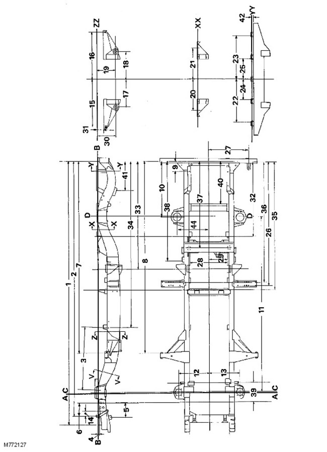
Chassis control dimensions
| No./letter | Size |
| A | Front dimensions |
| B | Chassis dimensions |
| C | Front axle centerline |
| D | Rear axle centerline |
| 1. | 4148 - 4143 mm |
| 2. | 4009.5 - 4005 mm |
| 3. | 978.7 - 981.2 mm |
| 4. | 22 - 20 mm |
| 5. | 252 - 250 mm |
| 6. | 239 - 236.5 mm |
| 7. | 3023.3 - 3022.3 mm |
| 8. | 3030.7 - 3028.7 mm |
| 9. | 155 - 153 mm |
| 10. | 871.2 - 869.2 mm |
| 11. | 2794 mm - Wheelbase |
| 12. | 488 - 482 mm |
| 13. | 488 - 482 mm |
| 14. | 82 - 79.5 mm |
| 15. | 750.9 mm |
| 16. | 750.9 mm |
| 17. | 440.5 - 435.5 mm |
| 18. | 440.5 - 435.5 mm |
| 19. | 299.5 - 295.5 mm |
| 20. | 500 - 495 mm |
| 21. | 500 - 495 mm |
| 22. | 594.2 - 593.4 mm |
| 23. | 594.2 - 593.4 mm |
| 24. | 283 - 282.2 mm |
| 25. | 283 - 282.2 mm |
| 26. | 1970 - 1968 mm |
| 27. | 642.9 - 639.5 mm |
| 28. | 750.9 mm |
| 29. | 290.5 mm |
| 30. | 295.5 mm |
| 31. | 299.5 - 295.5 mm |
| 32. | 103 - 100 mm |
| 33. | 1177.5 - 1175.5 mm |
| 34. | 1692.5 - 1689.5 mm |
| 35. | 2610 - 2606 mm |
| 36. | 2040.5 - 2037.5 mm |
| 37. | 1912.5 - 1909.5 mm |
| 38. | 1359 - 1357 mm |
| 39. | 1573 - 1571 mm |
| 40. | 270 - 268 mm |
| 41. | 665.5 - 663.5 mm |
| 42. | 440 - 438 mm |
| 43. | 32.25 - 31.25 mm |
The VV section runs along the engine mounts. The dimensions correspond to the dimensions for installing the engine for the 90 chassis.
Chassis 130

Chassis control dimensions
NOTE: The above dimensions are for the Land Rover 130 chassis frame. For additional dimensions please refer to the Land Rover 110 chassis frame drawing and control dimensions.
| No./letter | Size |
| A | Front dimensions |
| B | Chassis dimensions |
| C | Front axle centerline |
| D | Rear axle centerline |
| E. | Chassis Dimensions, Section AA |
| 1. | 663.0 mm, for reference only |
| 2. | 3569.3 - 3567.3 mm |
| 3. | 2421.8 - 2419.8 mm |
| 4. | 2317.5 - 2314.5 mm |
| 5. | 2188.3 - 2185.3 mm |
| 6. | 2119.5 - 2117.3 mm |
| 7. | 1990 - 1988 mm |
| 8. | 1970 - 1968 mm |
| 9. | 2401.8 - 2399.8 mm |
| 10. | 110.0 mm, for reference |
| 11. | 149.7 - 146.7 mm, reference size |
| 12. | 3225.8 mm, wheelbase |
Clearance and Tolerance Information
The following information is intended to guide technicians in the installation of exterior panels and body trim. Its purpose is to ensure proper alignment of the components and an acceptable appearance of the vehicle.
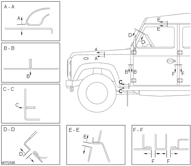
- Section AA, gap between bonnet and wing A = 3 - 8 mm. Parallelism within 2 mm must be ensured
- Section BB, gap between wing and lower part of pillar "A" B = 0 mm. Tolerance = ±1 mm
- Section CC, gap between wing and threshold C = 0 mm. Tolerance = ±1 mm
- Section DD, gap between window opening and door frame D = 5 - 9 mm
- Section EE, gap between door frame and roof E = 7 - 11 mm
- Section FF, gap between front/rear door and 'B'/'C' pillar F = 7 - 11 mm
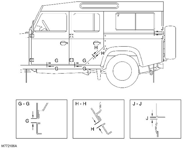
- Section GG, gap between door and threshold G = 7 - 11 mm. Door edge relative to threshold = 0 + 2 mm
- Section HH, gap between rear door and body H = 7 - 11 mm Door edge relative to body = 0 + 3 mm
- Section JJ, gap between the lower side part of the body and the body J = 0 - 4 mm Parallelism must be ensured within 2 mm
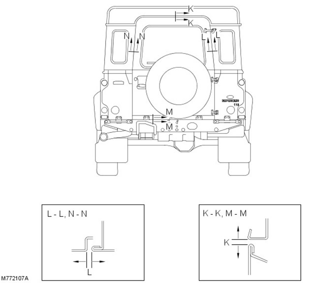
- Section KK, gap between roof and luggage compartment door K = 7 - 9 mm. Tolerance = ±1 mm
- Sections LL and NN, gap between the body side and the luggage compartment door L = 6 - 7 mm. Tolerance = ±1 mm
- Section MM, gap between rear part of body and luggage compartment door M = 7 - 9 mm
Comments on this article