Contents: Introduction ⇩ Car design ⇩ High-strength steel grades ⇩ Use of ultra-high-strength steel in…⇩ Aluminum ⇩ Use of aluminum in body construction ⇩ Magnesium ⇩ Application of magnesium in body…⇩ Collision Damage and Diagnosis ⇩ Changing the size of gaps ⇩ Planning a renovation ⇩ Receiving spare parts ⇩ Repair with editing ⇩ Straightening ⇩ "Fine" straightening with an…⇩ Cutting out body elements ⇩ Milling of spot welds ⇩ End grinding wheel ⇩ Short stroke saw ⇩ Reciprocating saw ⇩ Carrying out repair work ⇩ Replacing the rear body panel ⇩ Butt joint ⇩ Alignment and execution of a tack…⇩ Correct sequence for performing tack…⇩ Precautionary measures ⇩ Contact spot welding ⇩ MIG/MAG welding ⇩ Electric rivet welding (plug weld) ⇩ Glazing with glue ⇩ Installing glass with glue ⇩ Removal and installation of windows…⇩ Protective equipment and safety…⇩ General safety rules for body repair ⇩
Introduction
In the process of releasing new models, which replace each other faster and faster, the body plays a significant role. Different groups of customers are attracted, first of all, by the design and shape of the body. At the same time, the strength of the body plays the most important role in ensuring the safety of the driver and passengers. Modern Land Rover car bodies are characterized by the use of alternative materials: composite materials and plastics in combination with well-thought-out connection technologies.
Modern factory technologies allow us to manufacture bodies with safety frames almost without any problems. (load-bearing bodies). To ensure a high level of quality, mechanical strength tests of materials, numerous computer simulations, body collision tests are carried out, and advanced material production technologies are used. All repair work must be carried out in accordance with factory quality standards. This requires equipping technical centers with modern equipment and places special demands on the qualifications of technical personnel. To ensure high-quality body repair, knowledge of the factory technologies used and constant training in new repair methods and technologies are required. Repair manuals dedicated to specific models and a description of general repair techniques provide invaluable assistance in performing body repairs.
Strictly follow the repair technology described in this Manual. Failure to follow the repair technology may result in a serious reduction in the vehicle's safety level. After completing the repair work, it is necessary to ensure compliance with all the provided safety standards.
Car design
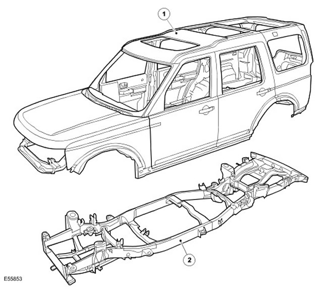
| Item name | Spare part catalog number | Description |
| 1 | Body type | |
| 2 | Body frame |
High-strength steel grades
Most modern cars are manufactured using different grades of steel, which allows for the optimization of the body structure. (collision, safety, rigidity, fuel economy, etc.).
Steels are divided into several groups according to tensile strength and yield strength. (force that results in plastic deformation of the material).
Yield strength
The yield point is the force at which the metal loses elasticity and begins to deform plastically without subsequent restoration of shape.
Tensile strength
The tensile strength is the force at which a stretched specimen breaks.
| Abbreviation | Steel grade | Yield strength |
| SS | Soft (low carbon) steel | Yield strength not more than 220 MPa |
| DP | Dual phase steel | Steel with yield strength up to 400 MPa |
| HS | High strength steel | Steel with a yield strength of 220 -450 MPa |
| EHS | Super high strength steel | Steel with a yield strength of 450-800 MPa |
| UHS | Ultra-strong steel | Steel with yield strength up to 1400 MPa |
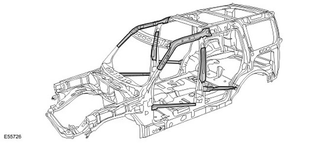
Ultra high strength
Ultra-high-strength steel elements used in the front and middle pillars of the body and the upper belt increase the body's resistance to deformation during frontal or side impacts.
Elements made of ultra-high-strength steel cannot be straightened due to their fragility.
Use of ultra-high-strength steel in the body structure
Aluminum
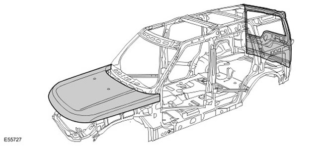
The hood, tailgate and trunk lid are made from 6000 grade aluminum. This is an aluminum alloy with magnesium and copper that undergoes heat treatment during production, increasing the strength of the panel and its resistance to dents.
When repairing aluminum parts, a separate set of tools should be used that should not be used when working with steel parts - this will avoid cross-contamination of metals.
Use of aluminum in body construction
Magnesium
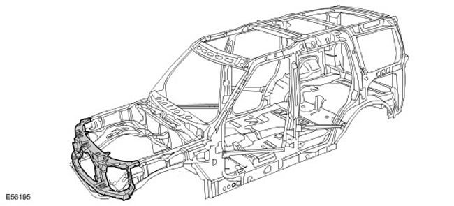
The hood latch panel is made of AM60B magnesium alloy. It has high viscosity and absorbs impact energy well. This alloy is also used to make the crossbar on which the instrument panel is mounted.
The bonnet latch panel must not be straightened or welded - in the event of an accident the panel must be replaced as a unit. If the anti-corrosion coating is damaged it must be restored using 'Land Rover Low Temperature Anti-Corrosion Coating', part number VEP 501 840 PMA.
Application of magnesium in body construction
Collision Damage and Diagnosis
General notes:
- Accurate diagnosis of the severity of damage ensures proper repair planning.
- All types of body repairs must be carried out in strict accordance with the instructions of the Body Repair Manual.
- When performing body repairs, the characteristics of the body's stability and strength should be taken into account. The body's design is calculated for specific deformation patterns that must not be changed during repair work.
- For example, crumple zones absorb a large portion of the impact energy during a collision. If any unprofessional methods or technologies are used to repair these zones, it may affect the safety of the vehicle.
- In addition to checking for external signs such as peeling paint, it is essential to check for hidden damage or deformation of the body that is not visible from the outside. To accurately assess damage to hidden body parts, it is often necessary to remove large attachments such as bumpers and inner fenders.
Another diagnostic option through visual inspection is to check the gap sizes. Any changes or disruptions in the relative position of the edges usually indicate a change in the size of the damaged parts.
Changing the size of gaps
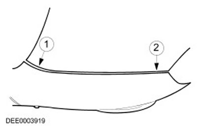
| Item name | Spare part catalog number | Description |
| 1 | Too big gap | |
| 2 | The gap is too small |
Planning a renovation
Before starting repairs, the following decisions must be made:
- Does the car need to be mounted on a stand or can it be straightened in another way?
- Is it necessary to carry out control measurements of the body?
- Is it necessary to remove components such as the engine or axles?
- What body parts need to be replaced?
- What body parts can be repaired?
NOTE: It is preferable to repair body parts rather than replace them, as this will preserve the integrity of the body.
Receiving spare parts
Availability of spare parts often determines how easily a body repair can be performed. The following procedure is recommended:
- Get all vehicle data including type, VIN, trim code, engine code, primary registration details, etc.
- Identify all metal parts that need to be replaced.
- Identify all attachments that need to be replaced, including small parts such as rivets, clamps, etc.
Repair with editing
Straightening repairs are often required to restore the original shape of the body after a collision. This can be done using:
- Stands for position verification
- Universal stand for straightening and measuring
Structure: The sequence of repairs depends on the individual repair plan (taking into account all necessary dismantling work). Clean the connection areas. Secure the vehicle on a suitable stand so as not to create stress in it. Mount the units on supports to relieve the load on the body. Select at least three measuring/attachment points that are not damaged and located as far apart as possible. (for basic adjustment). Check the dimensions at the measuring/fixing points.
- The sequence of repairs depends on the individual repair plan. (taking into account all necessary dismantling work).
- Clean the connection areas.
- Secure the vehicle to a suitable stand so as not to create stress in it.
- Place the units on supports to relieve the load from the body.
- Select at least three measuring/attachment points that are undamaged and located as far apart as possible. (for basic adjustment).
- Check the dimensions at the measuring/fixing points.
Editing: NOTE: During the editing process, constantly check the dimensions and clearances.
The body is always straightened in the direction opposite to the direction of impact. Always straighten with the body fully assembled. (do not cut out any elements in advance). Perform straightening in several stages. This eliminates the risk of over-tensioning the panels or breaking the welds. At each individual stage of straightening, try to relieve the tension from the parts subject to tensile load by hitting them with an aluminum hammer. (previously identified deformations, dents, welds, etc.)
NOTE: During the straightening process, constantly check the dimensions and clearances.
The body is always straightened in the direction opposite to the direction of impact. Always straighten with the body fully assembled. (do not cut out any elements in advance). Perform straightening in several stages. This eliminates the risk of over-tensioning the panels or breaking the welds. At each individual stage of straightening, try to relieve the tension from the parts subject to tensile load by hitting them with an aluminum hammer. (previously identified deformations, dents, welds, etc.)
CAUTION: The ultra-high-strength steel components used in the A-pillars, B-pillars and upper strut are not straightenable.
Straightening
Basic principles of panel straightening:
- Before replacing any sections or completely replacing body panels, always check carefully whether the damaged panel can be straightened by body straightening.
- Straightening is usually the easiest and most cost-effective method of repairing a damaged panel.
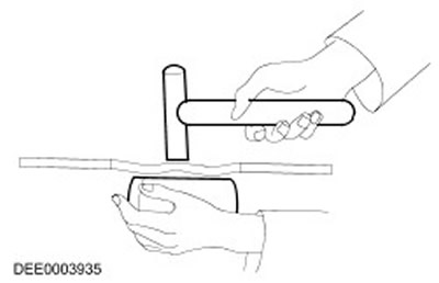
- Aluminum Hammer and Mallet Advantage: Less chance of overstretching the panel. Used to repair small dents in panels that are accessible from both sides. These two panel straightening tools are typically used for "finishing" repair operations.
- Advantage: low probability of excessive panel stretching.
- Used to repair small dents on panels that are accessible from both sides.
- These two panel straightening tools are typically used for "finishing" repair operations.
"Fine" straightening with an aluminum hammer and a universal underlay stamp
Swing Hammer If the damaged panel is only accessible from the outside, use a swing hammer to restore the panel to shape. The discs or pins required to mount the swing hammer are welded to a bare metal surface. Dents in the panel can be straightened out by controlled application of the swing hammer.
- If the damaged panel is accessible only from the outside, use a hammer with a sliding striker to restore the panel to its shape. The disks or pins required to mount the hammer with a sliding striker are welded to the surface cleaned to bare metal. Dents in the panel can be straightened out by controlled application of the hammer with a sliding striker.
Cutting out body elements
Depending on the elements being installed, different tools should be used to cut or separate body parts.
NOTE: All other components such as interior trim, window glass, etc. should be protected from flying sparks.
NOTE: Make sure to set the milling depth correctly to avoid weakening the remainder of the flange.
Milling of spot welds
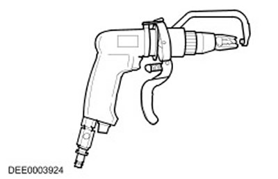
- End grinding wheel
NOTE: Wear protective clothing. Protect all vulnerable body parts or glass from flying sparks. Remove explosive materials from the work area.
Spot welds that cannot be removed by milling (diameter > 8 mm) should be selected using a grinding wheel. The same applies to spot and regular welds made using MIA technology.
NOTE: Wear protective clothing. Protect all vulnerable body parts or glass from flying sparks. Remove explosive materials from the work area.
Spot welds that cannot be removed by milling (diameter > 8 mm) should be selected using a grinding wheel. The same applies to spot and regular welds made using MIA technology.
End grinding wheel
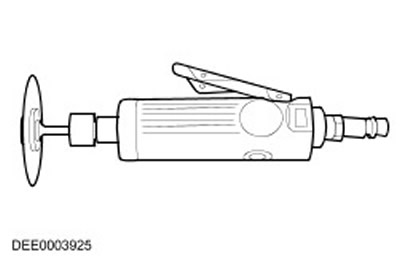
NOTE: Be careful not to damage metal components, wiring harnesses, hoses, etc. located underneath the part being cut out, remove them beforehand if necessary.
Bodywork saws are versatile and therefore well suited for cutting bodywork components.
Short stroke saw
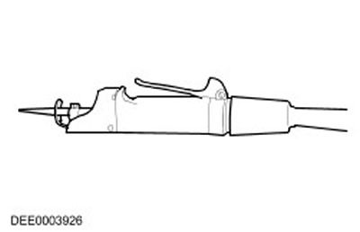
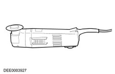
Reciprocating saw In addition to the short stroke saw, a reciprocating saw can also be used. It allows you to make narrow and straight cuts to a precisely specified depth.
In addition to the short stroke saw, you can also use a reciprocating saw. It allows you to make narrow and straight cuts to a precisely specified depth.
Reciprocating saw
Carrying out repair work
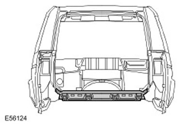
Complete replacement When complete replacement is performed, the entire damaged "old" element is separated at its joints and then the new element is installed entirely. The figure below shows the new replacement rear panel.
In a complete replacement, the entire damaged "old" element is separated at its joints and then the new element is installed entirely. The figure below shows the new replacement rear panel.
Replacing the rear body panel
Partial replacement It is often technically and economically feasible to perform a partial replacement. The two main criteria are, firstly, preserving the original body structure, and, secondly, reducing the cost of repairs to a minimum.
Often, from a technical and economic point of view, it makes sense to perform a partial replacement. The two main criteria are, firstly, preserving the original body structure, and, secondly, reducing the cost of repairs to a minimum.
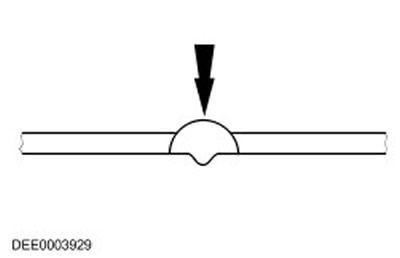
Basic Partial Replacement Technique: Butt Joints The new and old parts are joined by a continuous weld using MIG technology. Butt joints are typically used for partial replacement of framing members and posts or other members with short cut lengths.
- Butt joints.
- The new and old parts are joined by a continuous weld using MIG technology.
- Butt joints are typically used when partially replacing framing members and studs or other members with short cut lengths.
Butt joint
NOTE: Cuts for partial replacement should be as short as possible. Cuts may only be made along the cutting lines shown in the repair diagrams. Cuts must not be made near reinforcements or along specified fold lines.
Prepare the parts remaining on the car and the new parts. Using a hammer and a mandrel, restore the original shape of all mating surfaces on the deformed body parts remaining on the car (ensure that the shapes of the "old" and new parts match each other). Grind off the remaining spot or regular welds using the appropriate tool. Cut the new parts to shape. If necessary, punch or drill holes for MIA welding.
NOTE: Do not use a welding torch to remove paint residue. (heating can cause deformation of the metal).
Clean the mating flanges down to bare metal on both sides. Do not use an angle grinder for this purpose. (this can weaken the metal and damage the zinc layer.). Tools required: Rotary wire brush, belt grinder or plastic disc. Apply a sufficient amount of welding primer to the surfaces to be welded. Stir the primer thoroughly before use.
- Using a hammer and a mandrel, restore the original shape of all mating surfaces on the deformed body parts left on the car (ensure that the shapes of the "old" and new parts match each other). Grind off any remaining spot or regular welds using the appropriate tool.
- Cut out new pieces to shape.
- If necessary, punch or drill holes to perform MIA welding.
- Clean the mating flanges down to bare metal on both sides. Do not use an angle grinder for this purpose. (this can weaken the metal and damage the zinc layer.). Tools needed: Rotary wire brush, belt sander or plastic disc.
- Apply a sufficient amount of welding primer to the surfaces to be welded.
- Mix the primer thoroughly before use.
NOTE: Do not use a welding torch to remove paint residue. (heating can cause deformation of the metal).
NOTE: When using aerosols, be careful not to contaminate adjacent areas.
Fastening the new part:
- It is necessary to precisely adjust the new part to the specified dimensions. For this purpose, it is recommended to use the following tools:
- Verification stand
- Universal measuring system
- Assembly stand
- Ruler or tape measure
- At this stage, all the bodywork attachments that require precise fit and installation are installed, such as bumpers, seals, headlights, taillights, and locking system components. Careless work can lead to water leaks, wind noise, and a significant amount of additional work.
- Check the alignment of the edges of the mating parts and check that the gaps are equal. (compare left and right sides). Make sure the shape of the car is maintained.
NOTE: The amount of additional work can be significantly reduced if the joining and tack welding operations are performed with due care.
- Depending on the situation, fastening can be carried out using the following methods:
- Clamps (set)
- Screw clamp (set)
- Self-tapping screws
- Tack welds
- Using the proper tools, align the edges of the replacement relief pieces. The edges are then tack welded to ensure proper alignment of the pieces.
Alignment and execution of a tack weld
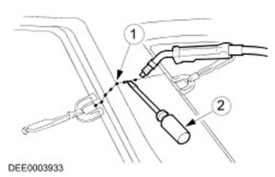
| Item name | Spare part catalog number | Description |
| 1 | Tack welds | |
| 2 | Perform alignment using proper tools |
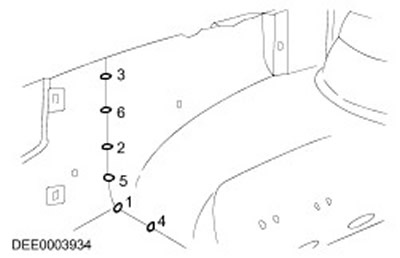
- Longer joints are usually made with tack welds to prevent distortion of the panel. It is important to perform tack welds in the correct sequence (see diagram).
- Weld the new part following the instructions in the repair manual.
Correct sequence for performing tack welding
Precautionary measures
- The electronic control modules (ECM) installed in the vehicle require special precautions when performing repair welding. The intense heat and vibration associated with welding can cause damage to the electronic modules. In particular, special precautions must be taken when removing or disconnecting the restraint control module (RCM). For more information, refer to Specifications (501-20B)
- Do not allow electronic modules or buses to come into contact with the ground or power supply of the welding electrode.
- Connect the ground connection of the electric welding equipment directly to the element to be welded. Make sure that there are no electrically insulating elements between the ground connection and the welding area.
Contact spot welding
Where resistance spot welding was used in the manufacture of the body, spot welding should also be used when replacing parts, if possible. In these new welded joints, the welding spots should be spaced 25 - 30 mm apart.
Equipment setup and selection of welding parameters:
- Equipment: Follow the equipment manufacturer's instructions to set up the equipment. Select the correct electrode holders. (as briefly as possible). Carefully adjust the position of the electrode holders and tips. The electrode tips should be convex. (pre-shape with a file and finish it with a grinding tool).
- To set up your equipment, follow the equipment manufacturer's instructions.
- Choose the right electrode holders (as briefly as possible).
- Carefully align the position of the electrode holders and tips.
- The tips of the electrodes must be convex. (pre-shape with a file and finish it with a grinding tool).
- Body: Make sure the mating flanges fit together exactly. Clean the mating surfaces down to bare metal. (inside and outside).
- Make sure that the flanges being connected are aligned exactly with each other.
- Clean the surfaces to be joined down to bare metal. (inside and outside).
- Notes on the method/technology: Perform a test weld on a sample of the material coated with welding paste. If there are any metal elements between the electrode holders, this will lead to a decrease in induction and, therefore, to a loss of power (adjust current settings). For high- and ultra-high-strength steels, individual power settings should be selected. Rewelding over old welds results in poor weld quality. Keep the electrode tips at an angle to the contact surface as close to 90° as possible. Electrodes work best if they have a convex shape. Clean the contact surface of the electrodes regularly.
- Perform a test weld on a sample of material coated with welding paste.
- If there are any metal elements between the electrode holders, this will lead to a decrease in induction and, consequently, to a loss of power. (adjust current settings).
Welding equipment used for body repair on modern Land Rover vehicles must be capable of reliably welding galvanised panels made of high-strength steel, consisting of three or more layers with a total thickness of up to 5 mm. If contact welding equipment does not meet these requirements, for safety reasons, electric rivet welding must be used. Electrical characteristics (current, resistance, heat) spot welding equipment specifications vary depending on the type of equipment. Therefore, it is important to follow the equipment manufacturer's instructions to ensure the actual welding process characteristics.
MIG/MAG welding
Equipment setup and selection of welding parameters:
- Any connections made during the manufacture of the vehicle using MIG/MAG technology must be connected by welding using the same technology during the repair process. In addition, individual contact welding points must be replaced with plug welds during the repair process.
- Partial replacement of contact welding points with plug welds (see above) is also performed when access is difficult or equipment for contact welding is not available at thicknesses over 3 mm. However, this leads to an increase in the time required to perform the operation and, accordingly, to higher requirements for corrosion protection.
- Welding repairs can only be performed properly if the equipment and all welding parameters are set up correctly.
- Equipment: Set up the equipment according to the manufacturer's instructions. Hoses must not be twisted. The core must not be contaminated with abrasive particles. Gas nozzles must not be clogged with slag and scale. Pay attention to the quality of the electrode wire and gas consumption.
- Adjust the equipment according to the manufacturer's instructions.
- The hoses must not be twisted.
- The core must not be contaminated with abrasive particles.
- Gas nozzles must not be clogged with slag and scale.
- Pay attention to the quality of the electrode wire and gas consumption.
- Body: Make sure the mating surfaces fit correctly. Clean the mating surface down to bare metal. Ensure proper clearances. (formation of suture roots).
- Make sure that the surfaces to be joined fit correctly.
- Clean the surface at the joint down to the metal.
- Ensure proper clearances (formation of suture roots).
- Notes on methodology/technology:
- Connect the ground cable near the welding area. (make sure the contact is good). When using a plug weld, to ensure high-quality penetration, you need to start welding from the bottom panel.
- Connect the ground cable near the welding area. (make sure the contact is good).
- When using a plug weld, to ensure high-quality penetration, you need to start welding from the bottom panel.
NOTE: The increased heat generated during MIG welding will destroy the weld primer/zinc layer over a larger area than with resistance spot welding, resulting in increased labor costs when applying subsequent anti-corrosion coating.
NOTE: To ensure that the weld is not just a surface bond, a test weld should always be performed.
NOTE: The increased heat generated during MIG welding will destroy the weld primer/zinc layer over a larger area than with resistance spot welding, resulting in increased labor costs when applying subsequent anti-corrosion coating.
NOTE: To ensure that the weld is not just a surface bond, a test weld should always be performed.
Electric rivet welding (plug weld)
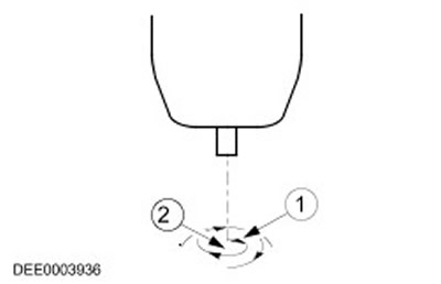
| Item name | Spare part catalog number | Description |
| 1 | Welding direction: circular movements, from inside to outside | |
| 2 | Welding start point: center of hole on bottom panel |
Glazing with glue
- The windshield, side windows and tailgate glass are fixed with glue directly to the window frames of the body and tailgate.
- Window panes are fixed in this way primarily due to the strength of the adhesive bond. Glazing on glue gives the body additional torsional rigidity.
Installing glass with glue
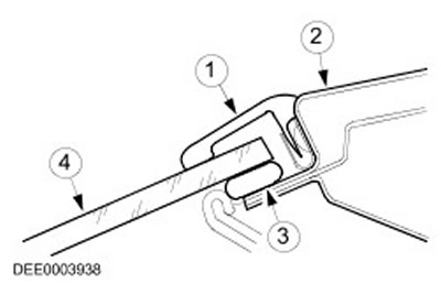
| Item name | Spare part catalog number | Description |
| 1 | Rubber band | |
| 2 | Window frame | |
| 3 | Glue | |
| 4 | Window glass |
Removal and installation of windows with glued glass
Precautionary measures
To prevent injury, follow these safety precautions:
- Use protective gloves.
- Use safety glasses.
- Before cutting a window with bonded glass, loosen and remove all hanging parts located in the cutting area that are exposed to danger, such as trim panels and moldings, as well as all electrical connections.
- Cover all painted areas located near the window.
- Trim off any excess glue as this will make cutting the glass easier.
- Secure the glass vertically to prevent it from falling out.
- Make cuts along the glue bead in easily accessible areas using a cutting tool.
- Carefully move the cutting tool around the perimeter of the window, cutting through the bead of adhesive.
- Do not touch the window frame or body flange.
- Use special "vacuum suction cups" to remove the glass from the window opening.
- Follow the manufacturer's instructions.
- Trim the remaining glue bead on the metal flange to a residual height of approximately 1 mm. After this, do not touch or clean the cutting surface.
- Carefully remove all damage to the paintwork (apply primer and topcoat).
- Replace window stops if necessary.
- Apply an even bead of adhesive to the window or body flange.
- Insert the glass into the window opening and center it. (2 mechanics required).
- Check the gaps.
- Use masking tape to protect the glass from falling out.
NOTE: While the adhesive on the window is drying, open the windows and doors and do not move the vehicle. (slamming doors creates excess pressure that can loosen window fasteners).
Final operations:
- Connect all electrical connections and check that the components are working properly.
- Install the attachments and check the accuracy and reliability of the fastening. Perform a visual inspection to ensure that the gaps and joints are uniform.
- Perform a visual inspection to ensure gaps and joints are uniform.
- Clean the window glass completely.
Protective equipment and safety precautions when performing work
When performing repairs, safety regulations and regulations must be observed. All occupational health and safety regulations must be observed.
Precautions when welding
- To prevent the risk of injury, observe the following precautions:
- Welder's mask (face protection)
- Protective shield
- Protective gloves
- Safety boots
- Extractor for welding fumes
- Welding should always be carried out in a well-ventilated area. A fire extinguisher should always be within reach.
General safety rules for body repair
Blowjob
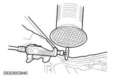
- Sealant, underbody protection, etc. should not be burned off with an open flame. This will result in toxic gases being released. For example, when PVC burns, gases containing hydrochloric acid are released. For this reason, appropriate extraction should always be used when grinding, welding or soldering.
- Always ensure good ventilation when working with materials containing solvents, use respiratory protection and suction equipment.
- When cutting, grinding or straightening metal, always wear hearing protection as noise levels can reach or exceed 85-90 dB(A).
- When removing parts from a vehicle on a lift, be aware of changes in the vehicle's center of gravity. When first placing the vehicle on a lift, be aware that it may need to be secured to prevent it from tipping over.
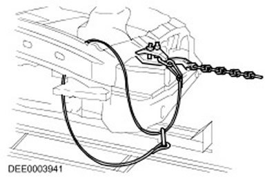
- During the straightening process, chains and chain clamps should be secured with safety cables.
Safety rope
Preparing for painting
Before performing paint repairs, thoroughly clean the vehicle using a steam cleaner or pressure washer.
Immediately before applying the paint coating, wash the repair areas with a weak solution of water and detergent and wipe them clean with solvent.
Be sure to clean the damaged areas down to the bare metal, with the cleaned area extending beyond the damaged area. Etch the bare surfaces with a phosphate primer to remove all rust residue and prepare the base for new paint coats. Re-treat the damaged surface with either an acid primer and two-component filler separately, or a combination acid primer/filler and apply a two-component paint coat. After applying the paint coat, treat the unpainted surfaces with an approved cavity wax.
CAUTION: When preparing to paint the bumpers, be careful not to damage the PDC sensors. If possible, remove only the clear coat. When painting the PDC sensors, do not apply too thick a layer of paint, as this may impair their performance.
CAUTION: When using heat-curing paint, the processing temperature should not exceed 65°C (149°F). Exceeding this temperature may cause deformation of the headlight and taillight reflectors and damage to other components.
Comments on this article