


Contents: Types of connections ⇩ Equipment for application ⇩ Corrosion protection ⇩ Cavity mastic ⇩ Sealants and adhesives ⇩
Types of connections
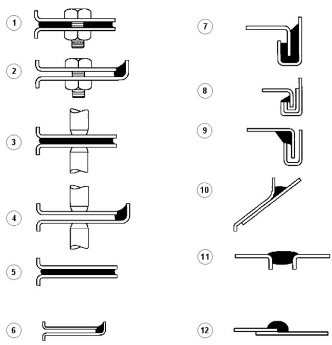
| Pos. | Spare No | Name |
| 1. | parts | Between panels with bolted fastening |
| 2. | - | Between the edges of the panels with bolted fastening |
| 3. | - | Between panels connected by spot welding |
| 4. | - | Between the edges of panels connected by spot welding |
| 5. | - | Between the panels being glued |
| 6. | - | Between the edges of the panels being glued |
| 7. | - | Seam joints (type a) |
| 8. | - | Seam joints (type b) |
| 9. | - | Seam joints (type c) |
| 10. | - | Gaps between panels (type a) |
| 11. | - | Gaps between panels (type b) |
| 12. | - | Lap joint |
| USING DESCRIPTION | SUPPLIER | SPARE PART NUMBER |
| CAVITY MASTICS | ||
| Mastic for internal cavities (transparent) | 3M | (08909, 08919, 08929) |
| Mastic for internal cavities (yellow) | 3M | (08901, 08911, 08921) |
| Mastic for anti-corrosion treatment of hidden cavities | Croda | (PW57) |
| MASTICS/VARNISHES FOR ENGINE COMPARTMENT | ||
| Atrolan engine compartment mastic and cosmetic mastic | Astors | DA3243/1 |
| Cosmetic mastic/varnish for engine compartment | Croda | PW197 |
| Cosmetic mastic/varnish for engine compartment | Dinal | 4010 |
| OTHER MATERIALS | ||
| Repair of elastic elements - rubber modified polypropylene parts | 3M | (05900) |
| Aerosol Auto Adhesive (trim) - adhesive mastic for decorative parts | 3M | (08080) |
| Waterproofing repair | Tereson | |
| Sound absorbing foam | Gurit Essex | Betacore 7999 |
| SEALANTS FOR SEAMS | ||
| Body sealing - gaps between panels (type b) | 3M | 08568 |
| Drip Check Clear - sealing of bolted joints, joints made by spot welding, adhesive joints, gaps between panels of type (a) and (b), folded joints of type (c) | 3M | 08401 |
| Drip Chek Heavy - gaps between panels, type (b), folded joints type (c) | 3M | 08531 |
| Polyurethane Seam Sealer - polyurethane based sealant for panel edges in case of bolted joints, joints made by spot welding, adhesive joints; gaps between panels of type (a) and (b), folded joints of type (c) | 3M | (08684, 08689, 08694) |
| Polyurethane sealant Polyurethane Sealer (sachet bag) | 3M | (08703, 08783, 08788) |
| Sprayable sealer - type 12 for lap joints | 3M | (08800, 08823) |
| Super seam sealer - type 12 for overlap joints of the highest quality | 3M | (08357) |
| Weld Thru Sealer - between panels joined by spot welding | 3M | (08625) |
| Betafill Clinch and Brushable Sealer for folding joints (black, gray, white) | Gurit Essex | 10211/15/20 |
| Seam sealant for seam joints and underbody coating "Clinch joint and underbody coating" (gray, beige) | Gurit Essex | (10101. 10707) |
| Leak Check Clear - sealing of panels in case of bolted joints, panel edges in case of joints made by spot welding and adhesive joints; folded joints type (c) | Kent industries | (10075) |
| Putty - gaps between panels of type (a) and (b) | Kent industries | |
| Polyurethane Seam Sealer - polyurethane based sealant for panels in case of bolted joints, panel edges in case of joints made by spot welding and adhesive joints; gaps between panels of type (a) and (b) | PPG | (6500) |
| Polyurethane Seam Sealer - polyurethane based sealant for panels in case of bolted joints, panel edges in case of joints made by spot welding and adhesive joints; gaps between panels of type (a) and (b) | Teroson | 92 |
| Terolan Light seam sealer - seam sealant for panel edges in case of bolted joints, joints made by spot welding, adhesive joints; gaps between panels of type (a) and (b); between the glued panels; for folded joints type (c) | Teroson | |
| Special brush-on joint sealant "Terosan Special Brushable Seam sealer" - overlap joints 12 | Teroson | |
| Aerosol Seam Sealant "Terostat Sprayable seam sealer" - sealant for panel edges in case of bolted, spot welded and adhesive joints; gaps between panels of type (a) and (b) | Teroson | 9320 |
| One-component polyurethane joint sealant "Terostat 1K PU" seam sealer (SE20) - for gaps between panels of type (a) and (b); for panel edges in the case of joints made by spot welding and adhesive joints | Teroson | |
| Sealing Compound - for panel edges in the case of bolted, spot welded and adhesive bonded joints; gaps between panels type (b) | Wurths | 8901001/-/6 |
| STRUCTURAL ADHESIVES | ||
| Automotive Structural Adhesive - for sealing adhesive joints of panels, type 5 and 7 | 3M | 08122 |
| Two Part Structural Epoxy (two-component epoxy resin) - for adhesive joints of panels and joints of panels made by spot welding, for folded joints of type (a) | Ciba Geigy | XB5106/7 |
| BOTTOM SEALANTS | ||
| Body Schutz | 3M | 08861 |
| Spray Schutz Aerosol Sealant | 3M | 08877 |
| Crodapol Brushable Sealer | Croda | PV75 |
| Terotex Underseal (CP02) (for underbody) | Terosan | 9320 |
| MASTICS FOR BOTTOM | ||
| Stone chip resistant coating (smooth) | 3M | 08158/9 |
| Underbody wax | Croda | PW61 |
| Underbody wax | Dinol | Tectacote 205 |
| PRIMER FOR WELDED JOINTS | ||
| Weld - thru coating | 3M | 05913 |
| Zinc spray | 3M | 09113 |
| Zinc rich primer enriched with zinc | ICI | P-565 634 |
Equipment for application
SATA Schutz Gun Model UBE
| Technical specifications | |
| Air flow | 200 l/min at 45 psi |
| Weight | 660 g |
The Sata Schutz Gun is approved for applying underbody protective coatings supplied in special 1L disposable containers. Most Schutz type containers are equipped with a threaded fitting (covering on the gun).
NOTE: Be sure to clean the gun after use with an appropriate solvent.
Complete operating instructions are included with the equipment.
Equipment for injection of mastic Sata HKD1 Wax Injection Equipment
The Sata HKD1 equipment is approved by Land Rover for use with cavity mastic. The equipment comprises a high quality forged gun with a 1 litre pressure feed container, a flexible nylon tip, a straight 1100mm steel tip and a slightly curved tip. The quick coupling, which is standard equipment, allows for easy tip changes. Each tip has its own characteristics in the shape of the "stream" to adapt to the specific type of box section being treated.
Sata HKD1 equipment has a 12-month warranty. All spare parts and service are provided by suppliers.
Cooper Pegler Falcon Junior Pneumatic (Airless) Equipment
The Falcon Junior air-powered sprayer, designed primarily for mastic application during transport, has a 5L container and a built-in hand pump. This high-quality unit provides a simple and effective way of spraying mastic without the need for an external compressed air source or other additional equipment.
A wide range of tips, nozzles and hoses together with a starter valve with a built-in filter ensures the possibility of using the sprayer in many specific applications. These include general maintenance, mastic injection and paint application. All elements are fully replaceable and provide a wide range of tip configurations.
Falcon Junior equipment is equipped with Viton seals and has a 12-month warranty.
3M Application Equipment
All 3M equipment is available through your local 3M paint equipment dealer or agent.
3M Caulking Gun 08002
Lightweight, rigid, metal frame gun is designed for a 325mm cartridge for applying sealants etc. This gun facilitates quick cartridge installation and has a quick release lever for precise control of material output and feed cut-off.
Pneumatic gun 3M Pneumatic Cartridge Gun 08012
Air-powered, air-powered gun for applying 3M cartridge materials. Provides superior ease of application of a smooth bead of sealant. Includes regulator for added control.
Other options for applying 3M materials:
3M Air Guns
Air-powered gun for dispensing 3M sealants in sachets (Part # 08006 for 200ml and 310ml sachets, and Part # 08007 for all sachet sizes including 600ml).
3M Applicator Gun 08190
For applying 3M Structural Adhesive 08120.
A gun for introducing mastic into internal cavities 3 Miner Cavity Wax Applicator Gun
It has a flexible hose 750 mm long and uses one-liter containers; this approved equipment is available from all 3M distributors.
Hand Gun for Heavy Duty Heavy Duty Manual Gun
Equipment and methods for introducing mastic into cavities
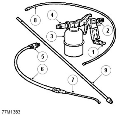
| Pos. | Spare No | Name |
| 1, | parts | Air inlet |
| 2, | - | Flow control (adjustment of the "jet" shape) |
| 3, | - | Syringe (capacity 1 l). Maximum pressure - 9.7 bar, 9.8 kg/cm²). |
| 4, | - | Gun connector |
| 5, | - | Connecting the tip nipple |
| 6, | - | Flexible tip |
| 7, | - | Rigid directional curved tip (conical, forward-facing "jet") |
| 8, | - | Flexible nylon tip 1100 mm with 360° "jet" |
| 9, | - | Rigid tip 1100 mm with 360° "jet" |
When re-treating areas where mastic has been injected and which have been damaged during repairs, it is necessary to use a compressed air gun with a built-in syringe and a set of interchangeable tips.
When using, the following points should be taken into account according to the installed accessories:
- When treating enclosed areas, use rigid or flexible tips that provide a 360° spray pattern for maximum coverage.
- If openings are restricted, use a curved tip to provide a more directed "stream".
1100mm Rigid Nozzle: The rigid nozzle produces a circular "stream" with a 360° spread in combination with a forward "stream". Although the mastic is distributed over all surfaces of the box section profile in one stroke, effective and complete coverage in long, straight structures and box section cavities is best achieved by spraying on both the forward and return strokes of the nozzle.
The rigid tip also provides the positional accuracy required in shaped section profiles, allowing visual assessment.
CAUTION: Do not insert the tip into access holes when using this accessory.
1100mm Flexible Nylon Nose: This nose has the same "jet" character as the rigid version, but provides the extra penetration needed for curved sections or where access is difficult. Its main limitation is the lack of positional accuracy within box section profiles.
Spray on the outward stroke of the tip. Withdraw the tip slowly to ensure adequate coverage. DO NOT withdraw the tip too quickly.
Keep the nylon tip tube away from the edges of the access hole to limit abrasion and extend the life of the tube. Be careful to stop spraying just before the tip emerges from the access hole. To make this process easier, paint the last 30 mm of the tip RED.
Curved Nozzle on Flexible Tip: The rigid curved nozzle produces a highly atomized, forward-facing, fully conical "stream" with long reach and good dispersion characteristics. This combination is well suited for targeted treatment of short, narrow sections and can also be used for direct spraying of material onto the inside of wheel arches etc.
Position the flat area on the end of the nozzle at an angle of 180° to the direction of the jet from the nozzle. This helps to direct the jet more accurately when it is hidden in a box section profile or in a process hole.
NOTE: Keep all mastic injection/application equipment clean. Use white spirit for cleaning immediately after mastic injection operations.
When spraying generally, move the tip in an arc from side to side to ensure complete coverage.
Precautions for body repair and rules for handling a car
Be careful when carrying out repair work at a service station. The PVC sealant coating of the underbody, the sealant seams, the mastic layer on the underbody and the body panels can be damaged if the vehicle is lifted carelessly.
Always follow proper lifting, jacking and towing procedures as shown in the Information section of GENERAL INFORMATION, paying particular attention to the following points:
Steam cleaning and de-waxing
Due to the high temperatures generated by steam cleaning equipment, there is a possibility that some finishes will be damaged and some adhesives and corrosion protection materials will be softened or liquefied.
Adjust the equipment so that the temperature at the nozzle outlet does not exceed 90°C. Be careful that the steam jet does not stop in one area and keep the nozzle at least 300 mm from the panel surfaces.
When performing repairs, DO NOT remove any mastic or clear coat from the underbody or lower engine area. If steam cleaning is necessary in these areas, recoat as soon as possible using mastic or other underbody protection material.
Corrosion protection
Below we detail the materials that are applied during manufacturing to provide corrosion protection.
Factory processing
During production, Defender is treated with the following anti-corrosion materials:
- A PVC based underbody sealant that is sprayed onto the underside of the floor, wheel arches and sill areas.
- A cavity mastic that is injected into body cavities and box-section profiles.
- A final coat of underbody mastic to cover the entire underside of the floor, including structural members but excluding brake discs, exhaust system and drive shafts.
- A layer of protective varnish applied to the entire body.
- A layer of protective mastic applied to the engine compartment and wheel arch areas.
NOTE: Do not apply mastic to the engine compartment on Td5 models.
In addition to the above measures, all steel elements are galvanized on both sides.
Bottom sealant
The underbody surface and the outer surfaces of the sills are treated with Plastisol PVC underbody sealant. This material is not suitable for re-application.
When repairing areas coated with underbody sealant, remove the factory applied material down to the appropriate break point, making sure to expose clean metal and have the edge of the existing material adhere cleanly to the panel.
CAUTION: Cover all suspension components, wheels, tires, powertrain, drive shafts, propeller shafts, exhaust system and brakes (including all attachment points) before applying new sealant to the underbody of the vehicle.
NOTE: Applying new underbody sealant should be done between priming and painting. Treat areas where seam sealant is used, if necessary, before applying underbody sealant.
Before applying sealant to the bottom, you MUST install plugs and rubber stoppers into the floor panel (except for the plugs that close the holes for injection of mastic). Heat sealing plugs that have been damaged should either be replaced with new ones installed with a heat gun or replaced with rubber sealing plugs.
Cavity mastic
Cavity mastic is incorporated into some box section sections. The information provided on the following pages is intended as a guide. It also shows the areas to be treated with cavity mastic and the access holes used in the manufacture.
Mastic for the underbody
A layer of underbody mastic is applied to the entire underbody, to the inside of the vertical flanges of the lower trim panels, and covers all moving and flexible parts, with the exception of the wheels and tires, brakes, and exhaust system. The mastic is applied over the underbody sealant and paintwork.
CAUTION: Old underbody sealant must be completely removed from an area extending at least 200mm beyond the area where new underbody sealant is to be applied.
The underbody protection mastic should be restored after all repairs affecting the floor panels.
Mastic for engine compartment protection
Using approved material, restore engine compartment protection mastic damaged during repair.
Wheel arch protection mastic
Using approved material, restore the wheel arch protection mastic damaged during repair. Enamel/primer, resistant to impact of gravel
Re-treat all areas protected by the factory impact protection primer using a suitable approved repair material.
Inspections during service maintenance
The Land Rover Factory Corrosion Protection Warranty requires that the factory protective coating be tested for corrosion by an authorised Land Rover Dealer at least once a year.
The list of service works includes the following actions aimed at checking the body for corrosion:
NOTE: Wash the vehicle and ensure it is free of deposits prior to inspection. It is the owner's responsibility to ensure that the vehicle is free of dirt build-up which could accelerate the effects of corrosion. If the customer delivers the vehicle to the shop in a dirty condition, the dealer MUST wash the vehicle prior to inspection, paying particular attention to areas that are difficult to access.
NOTE: The checks described above are visual only. This means that the operator should not remove trim panels, trim, wear strips or sound deadening material when checking the vehicle for paint damage and corrosion.
With the vehicle on a lift and using a test lamp or flashlight, visually inspect the vehicle for the following defects:
NOTE: Small blisters in the PVC skid plate sealant may be acceptable as long as no bare metal is exposed.
Particular attention should be paid to any signs of damage to panels or anti-corrosion material as a result of improper jack installation.
Proper procedures for using a jack and lifting a vehicle must be followed. See the Information section in GENERAL INFORMATION.
After lowering the vehicle, visually inspect it for signs of damage and corrosion in all painted areas, especially in the following areas:
Repair body damage and panel corrosion found during inspection as early as possible to minimize the damage area and ensure the effectiveness of the factory protective coating. When the cost of repair work must be agreed upon with the owner, the dealer must notify the owner and sign the appropriate documentation.
If corrosion has become obvious and is coming from under a removable element (for example, trim panels, window glass, seats, etc.), remove the element if necessary to ensure the effectiveness of the straightening.
Data taken from the website: lrman.ru
Repair of protective coating of the underbody
When performing body repairs, be sure to completely restore the sealant and the coating that provides protection against corrosion. This applies to both damaged areas of the body and to places where the protective coating was affected as a result of an impact in an accident or during repair operations.
Before straightening the panel, remove all corrosion protection material in the damaged area. This applies especially to panels coated with protective mastic, PVC-based sealant, sound-absorbing fillers, etc.
WARNING: DO NOT use oxy-acetylene equipment to remove corrosion protection materials. Combustion of these materials releases large quantities of vapors and gases.
Hard anti-corrosion sealant removal equipment can have different speeds and efficiencies. A compressed air scraper, (not a pneumatic chisel) offers a relatively quiet mechanical method of removing coatings using an extremely fast reciprocating motion. When using, guide the working end of the tool along the work surface.
The most common method is to use a heat gun with a built-in scraper.
CAUTION: The high temperatures generated by this equipment may cause smoke. Always use caution when using it.
Another tool that matches one of the most effective methods is the high-speed "hot knife". This tool uses a wide blade. It allows for quick work and is versatile.
It can be easily used in profiled sections that are otherwise difficult to access.
Use the following procedure when repairing the underbody coating:
Mastic for the underbody
NOTE: If the repair includes applying a topcoat of paint in areas that require underbody mastic, painting should be done before applying mastic.
After installing mechanical components including hoses, lines and small fittings, cover the brake rotors and apply a coat of approved underbody protection coating.
Mastic for the lower part of the engine compartment
When repairs involve replacing engine compartment panels, treat the entire engine compartment, including all fittings, clips and small hardware, with an approved engine compartment underbody varnish or wax.
Applying anti-corrosion coating at home
Owner-applied rustproofing in addition to factory treatment is not recommended as it will void the vehicle's rustproofing warranty. This does not apply to approved rustproofing mastics that are compatible with and can be applied over the existing coating.
Installation of approved equipment
When installing additional equipment, make sure that the protective anti-corrosion layer has not been damaged in the form of cracks or moisture access to body elements.
DO NOT drive self-tapping screws directly into the body panel, install the plastic inserts first. When drilling holes in panels, side members and other body components, always prime the edges of the holes with a suitable zinc or phosphoric acid primer, then brush on a sealant around the hole.
DO NOT attach unpainted metal surfaces of any accessory directly to the vehicle unless they are properly protected. When bolting metal surfaces together, always coat the joint surfaces with zinc primer, place zinc tape between the surfaces, or apply a layer of inert material.
Cavity mastic
This section shows box section sections treated with cavity mastic. Repairs involving these areas should include re-treatment with an approved cavity mastic using the access points shown. In addition, internal surfaces that have been touched by the repair, whether factory treated or not, should also be treated by injecting the mastic. This includes all box section members, cavities, door interiors etc. It is permissible to drill additional holes where necessary to gain access, but these should not be on load bearing members. These holes should be treated with a suitable zinc rich primer, brushed with mastic and then sealed with a rubber sealing grommet.
Before injecting the mastic, make sure that the cavities to be treated are free of dirt and foreign matter. If necessary, remove all dirt using compressed air.
Perform injection of mastic after applying the final paint coating.
During the treatment process, make sure that the mastic covers all flanges and seam areas and that it is applied to all repair areas of both old and newly installed panels.
NOTE: Cavity Putty should be applied AFTER touch-up painting is completed and BEFORE installing any decorative trim.
It should also be noted that new panels and body trim elements are supplied without mastic treatment, which should be done after repair.
Reliable protection of cavities with mastic is very important. Always follow these rules:
- Complete all topcoat applications before applying mastic.
- Before treatment, clean the body panel areas and blow out cavities if necessary.
- Maintain temperature at 18°C during application and drying.
- Check the spray cone shape of the cavity treatment equipment.
- Cover all areas that are to be covered with mastic and that may become contaminated by excess mastic.
- If there is a risk of contamination from mastic when spraying, remove components such as seat belt retractors.
- Raise the door windows all the way up before treating the inside of the doors.
- Treat body areas usually covered by trim elements before installing these elements.
- Clean the drain holes of the thresholds and doors after treating with protective mastic.
- Keep all equipment clean, especially spray nozzles.
The following figures show the treatment areas and injection holes for applying cavity mastic.
All zones symmetrically opposite to those shown are also processed.
Partition assembly
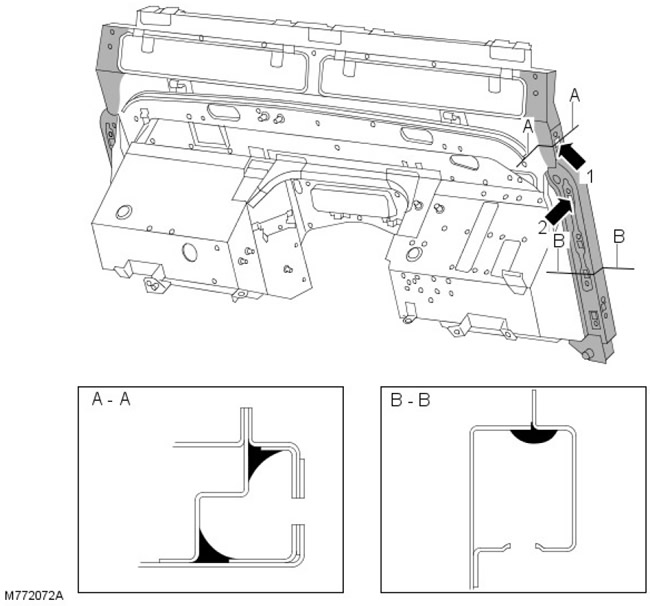
Sections AA and BB show the areas where the cavity mastic is applied. Arrows 1 and 2 show the holes for mastic injection.
'B/C' rack assembly
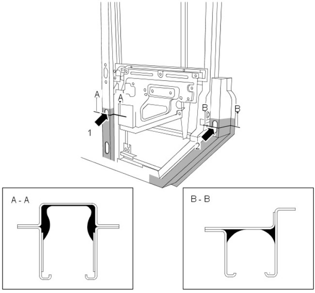
Section AA shows the application areas of mastic for the cavities on the 'B/C' pillar. Arrow 1 shows the hole for mastic injection.
Section BB shows the application areas of mastic for the cavities on the 'D' pillar. Arrow 2 shows the hole for mastic injection.
Front door
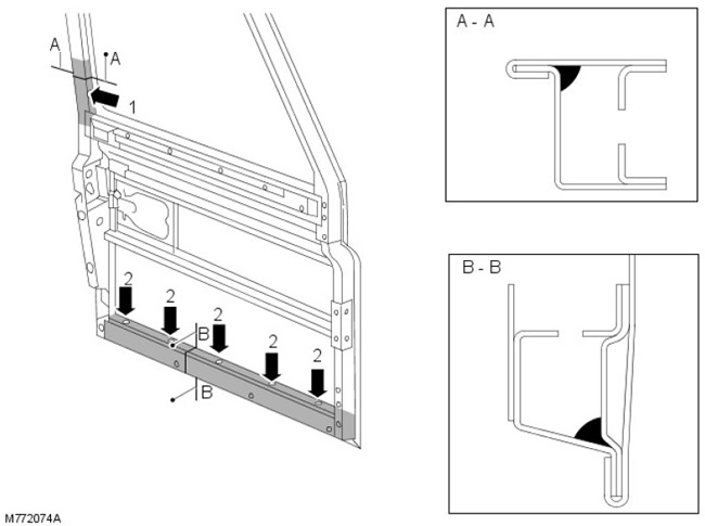
Sections AA and BB show the areas for applying mastic to the cavities on the front door. Arrows 1 and 2 show the holes for introducing mastic.
Back door
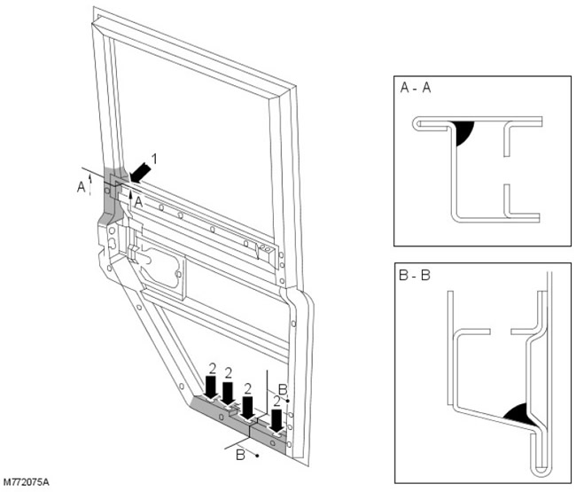
Sections AA and BB show the application areas of the cavity mastic on the rear door. Arrows 1 and 2 show the holes for mastic injection.
Sealants and adhesives
Structural adhesive
Metal adhesive is applied to critical seams during factory body assembly. It uses high-temperature application of a heat-curing nitrile phenol-based material. The material bonds two metal surfaces together, while also acting as a sealant that prevents dirt, moisture and gases from penetrating the joint. This material is not suitable for service use and should be replaced with a suitable medium-strength adhesive during repairs.
When separating a joint treated with metal adhesive, to avoid distortion, it is recommended to gently heat the joint until it is loosened enough to allow the panels to be separated.
NOTE: DO NOT perform MIG welding on a joint area that has been treated with metal adhesive until all traces of adhesive have been removed.
The following figures show the areas where the structural adhesive is applied. All areas symmetrically opposite to those shown are also treated.
Cross Closing Panel
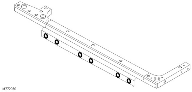
Structural adhesive applied around the lower side openings in the body.
Seam sealants
Plastisol heat curing PVC sealant is applied to joint areas during factory assembly. This material is not suitable for service use.
Sealing the joint should be done after applying the primer and before applying the filler and final paint coat. First clean the surfaces of grease and oil. Apply the sealant to the joint in a bead form either by hand or with a gun. If necessary, brush the sealant into the joint and smooth it out with a cloth dampened with a solvent such as Shell SBP3. This will give an acceptable cosmetic finish.
After repair, apply sealant to ALL accessible joints. Be aware that vehicle damage can often result in deflections in areas of the body that are remote from the impact site. Therefore, the sealant seams in these areas may be damaged during subsequent straightening and repair operations. Inspect the joints near the repair area for damage to the sealant seam, clean them if necessary, and reapply fresh sealant according to the following procedure:
If the joints are not accessible after assembly or installation of the components, apply a paste-type sealant to such joints. Some seams become inaccessible after the repair of panels is completed. In such cases, the application of paint and sealant should be done before final assembly.
If access permits, sealant should be applied to the repair joint on both sides. If access is limited to one side only (for example, in box-section profiles), introduce cavity mastic into the box-section element in question.
CAUTION: ALWAYS use a fume hood to remove toxic fumes when using oxy-acetylene equipment to remove panels treated with mastic and sealants.
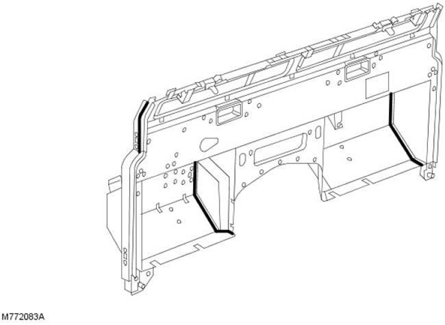
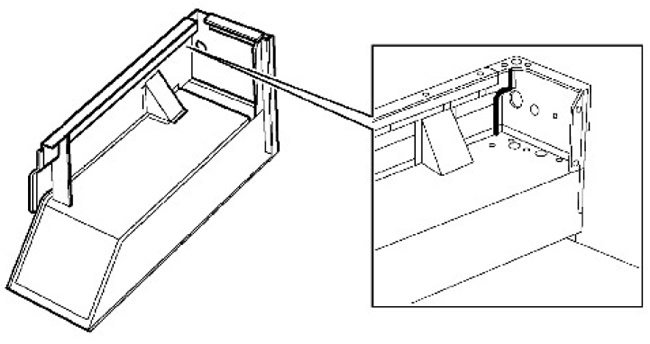
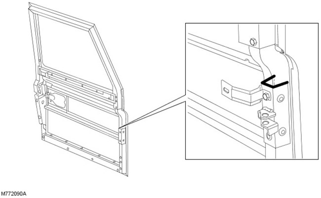
The following figures show the areas to be treated with joint sealants.
All zones symmetrically opposite to those shown are also processed.
Sealing the seam on the bulkhead assembly - front view
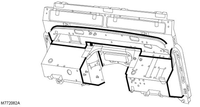
Sealing the seam on the bulkhead assembly - rear view
Sealant for seams on the side of the body
Seam sealant for the front door
NOTE: A joint sealant that should be smoothed out after application for cosmetic purposes.
Seam sealant for rear body
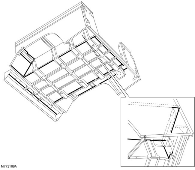
CAUTION: Avoid clogging drain holes when applying seam sealants.
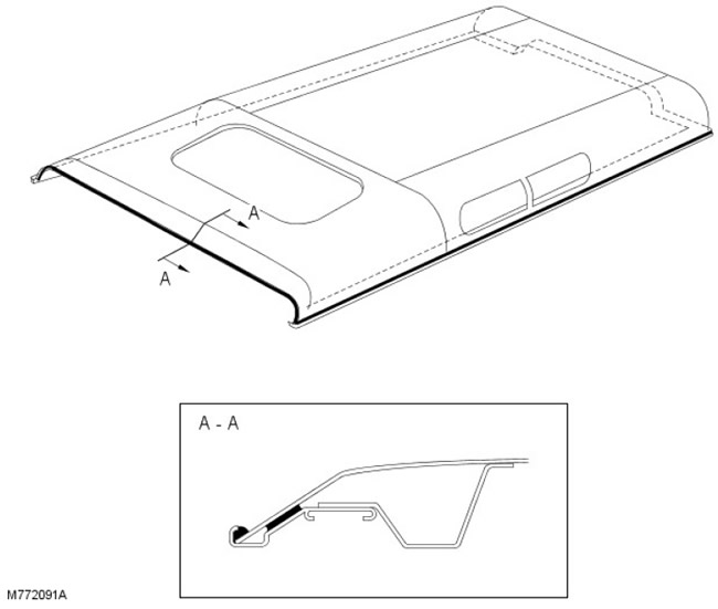
Roof Seam Sealant
Putty application areas
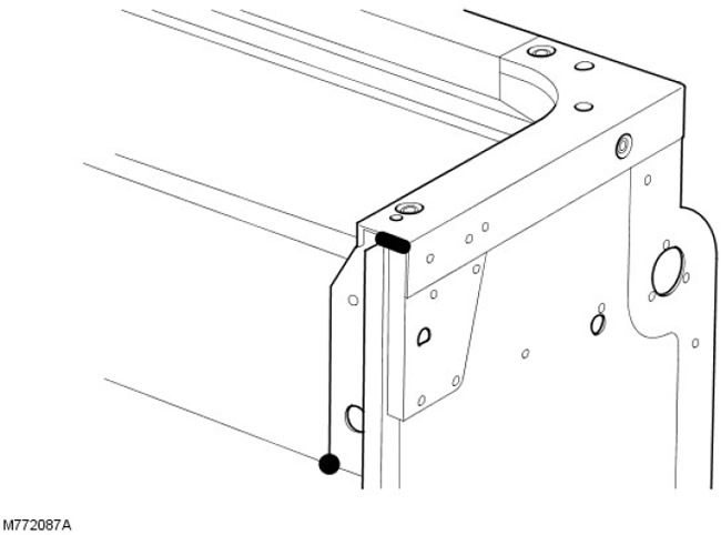
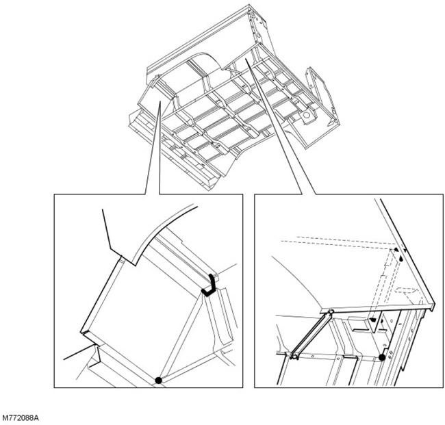
The following figures show the areas where the putty is applied. All areas symmetrically opposite to those shown are also treated.
The location of the putty on the partition
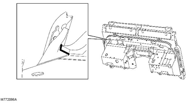
Putty placement on the back
The location of the putty on the underside of the car
The location of the putty on the front door
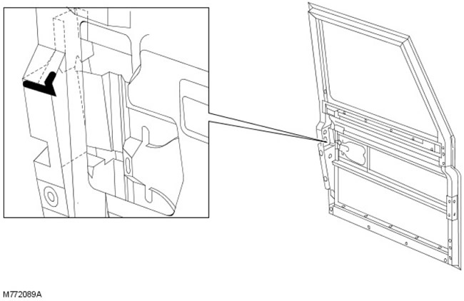
Foam/Rubber Sealant Application Areas
The following pictures show the areas where foam/rubber seals are placed. All areas symmetrically opposite to those shown are also treated.
Rear side part of the body
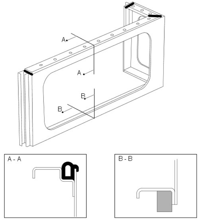
Section AA shows the rubber seal at the top of the rear side of the body.
CAUTION: Make sure the rubber seal is properly positioned in the channel.
Section BB shows the foam seal located on the lower edge of the upper rear quarter panel. It is secured to the panel with double-sided tape.
Lower side part of the body
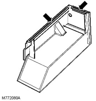
CAUTION: Seals are installed prior to assembly.
The arrows show the position of the two foam seals.
Comments on this article