Contents: Dismantling ⇩ Assembly ⇩
Dismantling
1. Raise the rear of the vehicle.
CAUTION: Do not work under a vehicle supported solely by a jack or lift. Always support the vehicle with safety stands.
2. Remove the wheel.
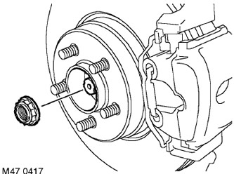
3. Remove the cotter pin from the hub bearing nut.
4. Ask your partner to press the brake pedal, unscrew the bearing nut and discard it.
5. Remove the brake disc.
BRAKE SYSTEM, REPAIR WORK, Brake disc - rear brake mechanisms.
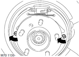
6. Remove the upper parking brake shoe tension spring.
7. Rotate the brake shoe retainers 90° and remove them.
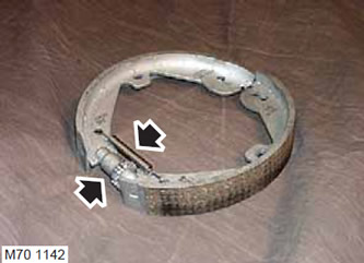
8. Remove the parking brake shoes assembly with the lower tension spring and clearance adjustment mechanism.
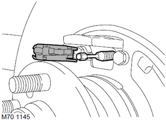
9. Remove the brake shoe expansion bar.
10. Remove the tie rod.
REAR SUSPENSION, REPAIR WORK, Transverse steering rod.
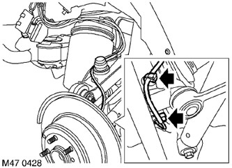
11. Release the wheel speed sensor wiring from the clamp.
12. Loosen the wheel speed sensor mounting bolt, release the sensor and move it to the side.
(The original source of the article is the website: www.LRman.ru)
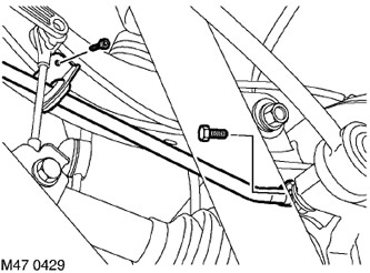
13. Loosen the Allen screw (allen type) fastenings of the parking brake cable bracket.
14. Remove the screw securing the cable to the brake disc protective cover.
15. Disconnect the cable from the protective casing.
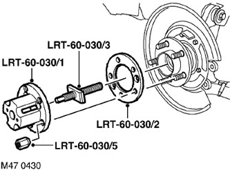
16. Screw the central screw LRT-60-030/3 onto the LRT-60-030/1 tool and install it on the hub together with the LRT-60-030/2 washer. Secure the tool with the LRT-60-030/5 nuts.
17. Tighten the center screw to press the drive shaft out of the hub.
18. Dismantle the tool.
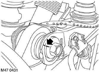
19. Mark the location of the eccentric relative to the upper arm.
20. Remove and discard the nut and bolt that secure the hub to the upper control arm. Disconnect the hub from the control arm.
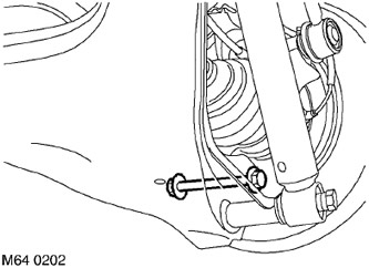
21. Remove and discard the nut and bolt that secure the lower suspension arm to the hub.
22. Remove the hub assembly.
Assembly
1. Clean the splines of the drive shaft and hub from dirt.
2. Lightly lubricate the spline surfaces.
3. Clean any dirt from the mating surfaces of the hub and upper and lower arms.
4. Install the hub assembly. Install a new bolt and insert the drive shaft into the hub.
5. Align the hub with the upper arm and install a new bolt. Install the eccentric according to the mark made earlier and tighten the bolt slightly.
6. Tighten the lower control arm to hub bolt to 250 N·m (184 lb ft).
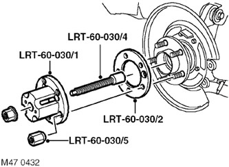
7. Install the LRT-60-030/4 tool on the drive shaft.
8. Install the LRT-60-030/1 tool together with the LRT-60-030/2 washer and secure the tool with the LRT-60-030/5 nuts.
9. Screw the nut onto the LRT-60-030/4 tool and tighten it to fully insert the drive shaft into the hub flange.
10. Dismantle the tool.
11. Attach the parking brake cable to the brake disc guard and tighten the bolt to 8 N·m (6 lb ft).
12. Position the parking brake cable bracket to the upper control arm and tighten the Allen screw to 5 N·m (3.7 lb ft).
13. Clean the surface of the wheel speed sensor, apply anti-seize lubricant to the sensor, and secure it to the hub.
FILLING CAPACITIES, USED OPERATING LIQUIDS, OILS AND SEALANTS, Lubrication system.
14. Install the Allen type screw for the wheel speed sensor and tighten it to 8 N·m (6 lb ft).
15. Install the tie rod.
REAR SUSPENSION, REPAIR WORK, Transverse steering rod.
16. Clean the protective cover and brake disc with brake cleaner.
17. Clean the brake shoe expansion bar.
18. Install the expansion bar.
19. Install the brake pads in place, secure the brake pad retainers and the upper tension spring.
20. Install the brake disc.
BRAKE SYSTEM, REPAIR WORK, Brake disc - rear brake mechanisms.
21. Install the new hub bearing nut and tighten it to 420 N·m (311 lb ft).
22. Secure the nut to the drive shaft.
23. Adjust the parking brake.
BRAKE SYSTEM, ADJUSTMENTS, Parking brake adjustment.
24. Reinstall the wheel and tighten the nuts to 140 N·m (103 lb ft).
25. Remove the supports and lower the vehicle.
26. Check the wheel alignment angles.
27. Tighten the upper control arm-to-hub bolt to 165 N·m (121 lb ft).
Comments on this article