Contents: Dismantling ⇩ Assembly ⇩
Dismantling
1. Raise the rear of the vehicle and install stands.
CAUTION: Do not work under a vehicle supported solely by a jack or lift. Always support the vehicle with safety stands.
2. Remove the wheel.
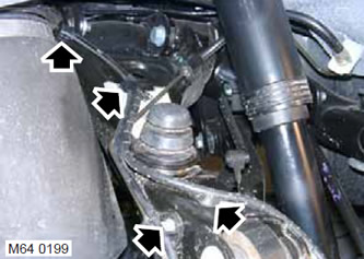
3. Disconnect the wheel speed sensor wiring from the upper control arm.
4. Remove the Allen screw securing the brake hose.
5. Place a jack under the shock absorber mounting bracket to support the lower control arm.
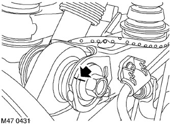
6. Mark the location of the eccentric relative to the upper suspension arm.
7. Remove and discard the nut and bolt that secure the hub to the upper control arm. Disconnect the hub from the control arm.
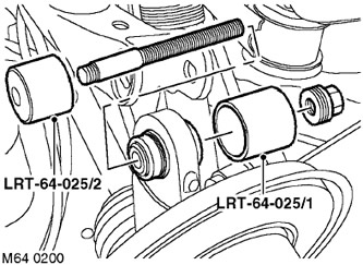
8. Remove the hinge using tools LRT-64-025/1 and LRT-64-025/2 (the picture shows the right side of the car).
Assembly
1. Clean the joint and the place where it attaches to the hub.
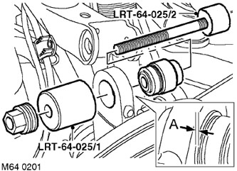
2. Using the LRT-64-025/1 and LRT-64-025/2 devices, install the hinge with the chamfer facing backwards so that it protrudes by the value 'A' relative to the machined surface (see fig.). The value of the protrusion 'A' = 0.75 mm (0.030 inches).
3. Align the hub with the upper arm and install a new bolt. Install the eccentric according to the mark made earlier and tighten the bolt slightly.
4. Install the Allen screw securing the brake hose to the upper control arm and tighten it to 5 N·m (3.7 lb ft).
5. Secure the wheel speed sensor wiring.
6. Reinstall the wheel and tighten the nuts to 140 N·m (103 lb ft).
7. Lower the vehicle.
8. Check the wheel alignment angles.
9. Tighten the upper control arm-to-hub bolt to 165 N·m (121 lb ft).
[The article is based on information from the website: www.LRman.ru]
Comments on this article