


Contents: Removal ⇩ Installation ⇩
Special tool
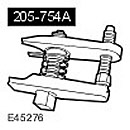 Ball Joint Puller 205-754(LRT-54-027)
 |
Removal
1.
CAUTION: Never work on a vehicle supported solely by a jack. Always support the vehicle securely.
Raise and support the vehicle.
2. Remove the wheel and tire assembly.
3.
CAUTION: Do not use excessive force to disconnect the height sensor connector.
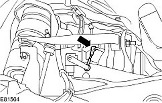
Disconnect the height sensor connector.
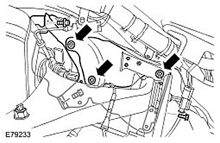
4. To gain access, remove the upper control arm and brake line heat shields. Remove the 3 nuts. Remove the 3 bolts.
5.
CAUTION: To prevent the ball joint from turning, use the supplied Allen key.
Loosen the stabilizer bar strut nut. Discard the nut.

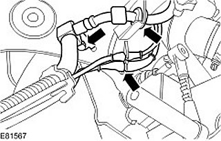
6. Disconnect the brake hose and wheel speed sensor wires from the upper control arm. Remove the bolt.
7.
CAUTION: To prevent the wheel knuckle from falling out and the inner axle joint from separating, support the wheel knuckle.
Loosen the upper control arm mounting nut.

8. Using a special tool, disconnect the upper arm ball joint. Unscrew and discard the nut.
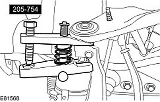
9. Remove the upper control arm. Unscrew the two nuts and tighten them.
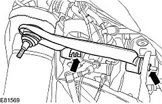
Installation
1. Install the upper control arm. Insert the bolts, but do not tighten them completely yet. Screw on new nuts.
2. Attach the upper control arm to the wheel knuckle. Screw on a new nut and tighten it. (tightening torque 70 Nm).
3. Secure the brake hose and wheel speed sensor wires to the upper control arm. Tighten the bolt. (tightening torque 23 Nm).
4. Secure the stabilizer bar strut. Screw on a new nut and tighten. (tightening torque 115 Nm).
5. Install the upper control arm and brake line heat shields. Install the three bolts. Install the three nuts.
6. Attach the height sensor connector.
7. Adjust the height distance between the center of the axle shaft end and the edge of the fender trim panel to 466 mm.
Comments on this article