Special tool
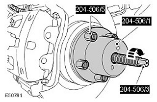
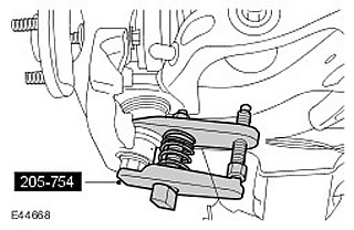
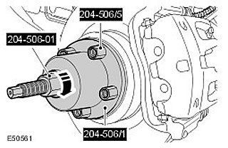
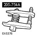 Ball joint puller 205-754 (LRT-54-027) Ball joint puller 205-754 (LRT-54-027) | 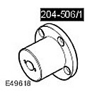 Device for removing/replacing axle shafts 204-506/1 (LRT-60-030/1) Device for removing/replacing axle shafts 204-506/1 (LRT-60-030/1) | 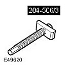 Device for removing/replacing axle shafts 204-506/3 (LRT-60-030/3) Device for removing/replacing axle shafts 204-506/3 (LRT-60-030/3) |
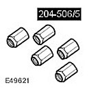 Holders - tool for removing/replacing axle shafts 204-506/5 (LRT-60-030/5) Holders - tool for removing/replacing axle shafts 204-506/5 (LRT-60-030/5) | 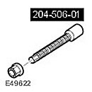 Adapter nick tool for mounting axle shafts 204-506-01 (LRT-60-030/4) Adapter nick tool for mounting axle shafts 204-506-01 (LRT-60-030/4) |
Removing
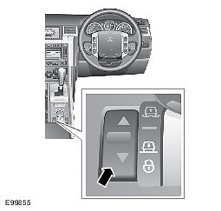
1. Set the car to landing height.
2.
WARNING: It is forbidden to carry out work on a vehicle supported only by a jack. Always place the vehicle on secure stands.
Raise and support the vehicle.
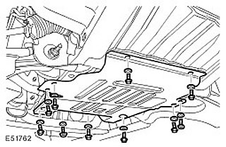
3. Remove the lower engine protection. Remove 10 bolts and washers.
4. Remove the wheel and tire assembly.
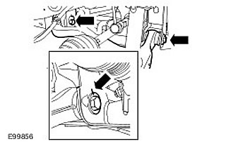
5. Disconnect the shock absorber assembly with an elastic element from the lower arm. Loosen the nut and remove the bolt.
6. Make notes to remember the positions of the bolts in relation to the chassis brackets. Turn out 2 bolts.
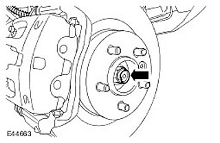
7. Loosen the axle shaft nut. Discard the nut.
8. Using the special tool, disconnect the axle shaft from the wheel hub.
9.
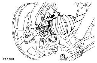
NOTE: Excessive bending can damage the lower arm ball joint. Failure to follow this instruction may result in vehicle damage.
Disconnect the axle shaft from the wheel knuckle.
10. Attach the axle shaft away from the lower arm.
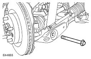
11. Loosen the lower ball joint nut.
12. Using the special tool, disconnect the lower ball joint from the wheel knuckle.
13. Remove the lower arm.
Installation
1. Install the lower arm. Insert the bolts, but do not fully tighten them yet.
2.
NOTE: Excessive bending can damage the lower arm ball joint. Failure to follow this instruction may result in damage to the vehicle.
Attach the lower arm to the wheel knuckle. Tighten the lower arm ball joint nut (tightening torque 115 Nm).
3. Release the axle shaft.
4. Using the special tools, install the axle shaft into the wheel hub.
5. Screw in a new axle shaft nut. Tighten the new axle shaft nut (tightening torque 350 Nm). Fasten the nut on the axle shaft.
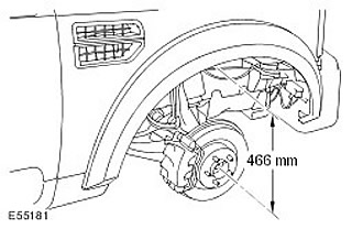
6. Adjust the height distance between the center of the end of the axle shaft and the edge of the fender trim panel to 466 mm.
7. Tighten the lower arm bolts (tightening torque 275 Nm). Align the bolts to the previously made marks.
8. Disconnect the shock absorber assembly with an elastic element from the lower arm. Tighten the nut and bolt (tightening torque 300 Nm).
9. Install the lower engine protection. Tighten the bolts (tightening torque 62 Nm).

10. Install the wheel and tire assembly. Tighten wheel nuts (tightening torque 140 Nm).
11. Adjust wheel alignment.
Comments on this article