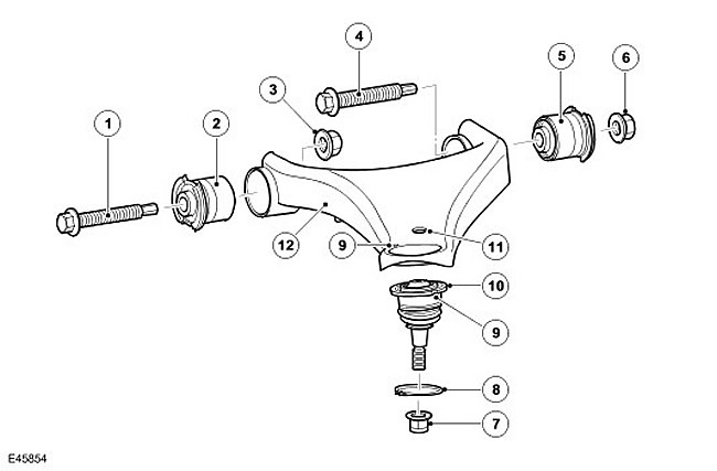
| Item name | Spare part catalog number | Description |
| 1 | - | Flange bolt |
| 2 | - | Sleeve |
| 3 | - | Self-locking nut |
| 4 | - | Flange bolt |
| 5 | - | Sleeve |
| 6 | - | Self-locking nut |
| 7 | - | Self-locking nut |
| 8 | - | Retaining ring |
| 9 | - | Installation marks |
| 10 | - | Ball joint |
| 11 | - | Mounting hole of stabilizer bar |
| 12 | - | Upper control arm |
The upper control arm assembly includes a control arm, two bushings, and a ball joint. The upper control arm is made of stamped steel. The outer end of the arm has a hole for the ball joint. A small recess next to the ball joint hole serves to properly orient the ball joint. A small hole near the ball joint is designed to attach the stabilizer strut. On the underside of the upper control arm, there is a bracket for attaching the height sensor arm and two additional brackets that serve to attach the brake hose, brake pad wear sensor, and wheel speed sensor cables.
At the inner end of the lever there are two bushing holders welded to the lever. A bushing is pressed into each holder. The bushings are located between the bosses on the chassis and are secured with bolts and self-locking nuts through metal inserts in the center of the bushings.
The ball joint is pressed into the upper control arm. The ball joint is fixed in place in a hole that prevents it from moving. A retaining ring holds the ball joint in the hole. There are two semicircular cutouts on the face of the ball joint. For the ball joint to work properly, one of these cutouts must be aligned with a small recess in the upper control arm.
Comments on this article