Contents: Removal ⇩ Installation ⇩
Special tool
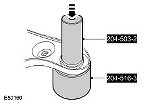
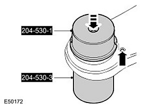
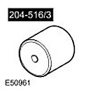 Ball joint puller 204-516/3 (LRT 64-026/3) Ball joint puller 204-516/3 (LRT 64-026/3) | 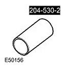 Ball joint puller 204-530-2 Ball joint puller 204-530-2 | 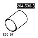 Ball joint installation tool 204-530-3 Ball joint installation tool 204-530-3 | 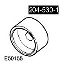 Ball joint installation tool 204-530-1 Ball joint installation tool 204-530-1 |
Removal
NOTE: This procedure describes the removal and installation of the upper control arm ball joint.
1. Remove the upper control arm. For more information, refer to Upper Control Arm (60.35.01)
2. Remove the dust seal. Remove the seal holder. Remove the retaining ring.
3. Remove the ball joint using special tools.
Installation
1.
CAUTION: Make sure the alignment marks are aligned.
Install the ball joint using special tools.
2.
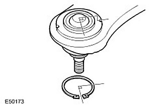
CAUTION: The snap ring cutout must be rotated 90 degrees relative to the alignment marks.
Install the retaining ring.
3. Install the upper control arm. For more information, refer to Upper Control Arm (60.35.01)
Comments on this article