Contents: Removal ⇩ Installation ⇩
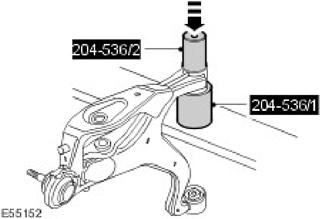
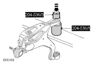
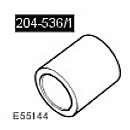 Receiver for front lower arm front bushing 204-536/1
 | 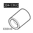 Front Lower Arm Front Bushing Remover 204-536/2
 | 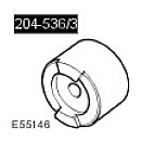 Front Lower Arm Front Bushing Mounting Tool 204-536/3
 |
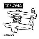 Ball Joint Puller 205-754(LRT-54-027)
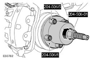
 | 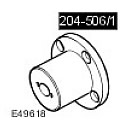 Device for dismantling/replacing half-shafts 204-506/1 (LRT-60-030/1)
 | 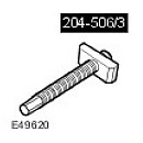 Device for dismantling/replacing half-shafts 204-506/3(LRT-60-030/3)
 |
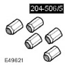 Holders - device for dismantling/replacing axle shafts 204-506/5(LRT-60-030/5)
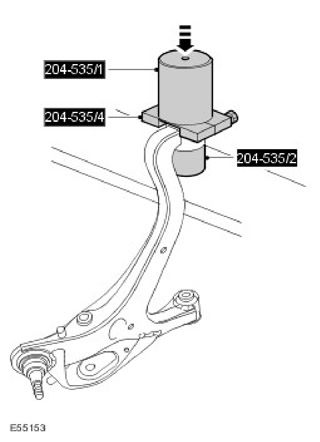
 | 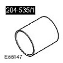 Receiver for rear lower arm bushing 204-535/1
 | 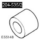 Lower Arm Rear Bushing Remover 204-535/2
 |
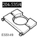 Lower Arm Rear Bushing Removal Tool Plate 204-535/4
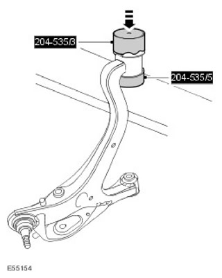
 | 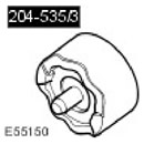 Mounting device for rear lower arm bushing 204-535/3
 | 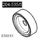 Lower Arm Rear Bushing Depth Adjuster/Mounter 204-535/5
 |
Removal
NOTE: Bushings should be replaced in pairs, left and right sides.
NOTE: Record the position in which the bushing is installed.
1. Make sure the tire pressure is correct and the vehicle has the correct ride height. For more information, refer to Ride Height Adjustment (60.90.03)
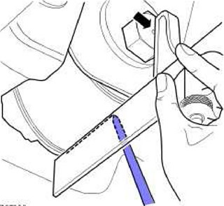
2. Mark the position of the bushing relative to the lower arm.
- Take a straightedge with a spirit level and set it so that it points straight down when aligned with the center of the lower arm rear bushing bolt head.
- Align the square's straight edge with the lowest point of the lower arm rear bushing installation lug circumference.
- Place a piece of masking tape on the control arm and draw a horizontal line along the underside of the lower control arm rear bushing lip. (parallel to the axis of the sleeve).
- Perform this procedure on both the right and left sides.
3.
CAUTION: Do not work on or under a vehicle that is supported only by a jack. Always support the vehicle securely.
Raise and support the vehicle.
4. Remove the wheels and tires.
5. Remove the right lower control arm. For more information, refer to Lower Control Arm (60.35.02)
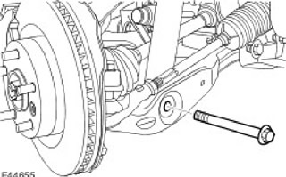
6. Disconnect the shock absorber and spring assembly from the left lower arm. Loosen the nut and remove the bolt.
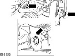
7. Make marks to indicate the position of the bolts in relation to the chassis brackets. Remove 2 bolts.
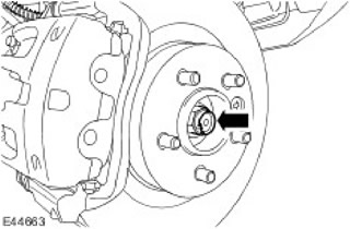
8. Loosen the left axle shaft mounting nut. Discard the nut.
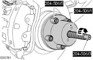
9. Using special tools, disconnect the left axle shaft from the wheel hub.
10.
NOTE: Excessive rotation at the ball joint may damage the lower arm ball joint. Failure to do so may result in vehicle damage.
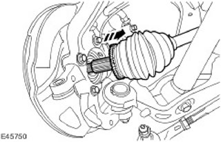
Disconnect the left axle shaft from the wheel knuckle.
11. Secure the left axle shaft away from the lower arm.
12. Loosen the left lower ball joint mounting nut.
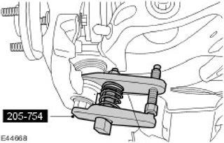
13. Using the special tool, disconnect the lower left ball joint from the steering knuckle.
14. Remove the left lower control arm.
15. Record the position of the bushing in relation to the lower arm.
16.
CAUTION: To remove the bushing, it is necessary to remove the bushing flanges.
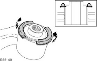
Remove the lower arm front bushing flanges.
17. Using special tools, remove and discard the front lower arm bushings.
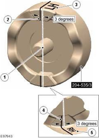
18. Apply guide lines to the installation tool (204-535/3).
- Mark the center line on the installation jig.
- Mark a line across the top surface at an angle of 3 degrees to the left of the center line.
- Marked 'LH' on top surface.
- Mark a line across the bottom surface at an angle of 3 degrees to the left of the center line.
- Marked 'RH' on the bottom surface.
19. Using special tools, remove and discard the rear lower arm bushings.
Installation
1.
CAUTION: Make sure the bushing is installed straight.
Mark the position of the bushing relative to the lower arm.
- Make sure the 'RH' or 'LH' line on the correct marked side of the special tool (204-535/3) is aligned with the marked line on the right or left bushing to be installed.
- Using a marker, extend the line from the special tool to the bushing. Using the drawn line, align the bushing relative to the lower arm before installing the bushing.
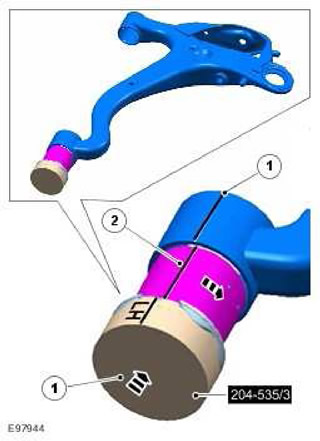
2.
CAUTION: Make sure the correct special tool is used to install the bushings to the correct depth.
Using special tools, install the rear lower arm bushings.
3.
CAUTION: Make sure the bushing is installed straight.
Using special tools, install the front lower arm bushings.
4. Install the left lower control arm. Screw in the bolts, but do not tighten them completely yet.
5. Attach the shock absorber and spring assembly to the lower arm. Tighten the nut and bolt to 300 Nm.
6. Release the axle shaft.
7. Using special tools, insert the left axle shaft into the wheel hub.
8. Tighten the new axle shaft mounting nut.
Tighten the new axle shaft nut to 350 Nm. (258 lbs/ft). Secure the nut to the axle shaft.
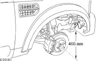
9. Set the height distance between the center of the end of the axle shaft and the edge of the wing trim panel to 466 mm.
10. Tighten the lower control arm bolts (tightening torque 275 Nm). Align the bolts with the marks made earlier.
11. Attach the shock absorber and spring assembly to the lower arm. Tighten the nut and bolt to 300 Nm. (221 lbs/ft).
12. Install the right lower control arm. For more information, refer to Lower Control Arm (60.35.02)
13. Install the wheels with tires. Tighten the wheel nuts to 140 Nm.
14. Adjust the wheel alignment angles.
Comments on this article