Contents: Removal ⇩ Installation ⇩
Special tool
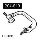 204-619 G-Clamp 204-619 G-Clamp | 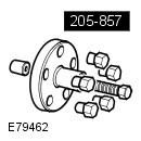 205-857 Remover, Halfshaft 205-857 Remover, Halfshaft | 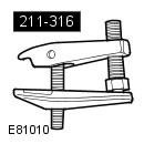 211-316 Separator, Ball Joint 211-316 Separator, Ball Joint |
Removal
1. Remove the mixing chamber panel. Refer to procedure: Mixing Chamber (412-01 Climate Control, Removal and Installation).
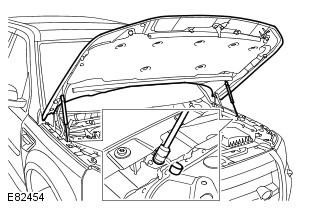
2. Release the hood support posts and secure the hood in a vertical position.
3. Raise and support the vehicle.
WARNING: Ensure that the vehicle is supported securely.
4. Remove the wheel and tire assembly. Refer to procedure: Wheel and Tire (204-04 Wheels and Tires, Removal and Installation).
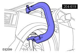
5. Compress the spring assembly with the shock absorber. Special tool(s): 204-619.
NOTE: This step requires the assistance of a second mechanic.
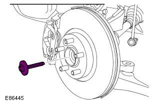
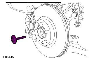
6. Remove the front axle bolt and discard it.
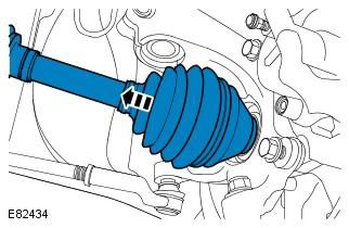
7. Partially release the front axle shaft from the steering knuckle. Special tool(s): 205-857
8. Partially release the front axle shaft from the steering knuckle.
CAUTION: To avoid damage to the ball joint, do not allow the axle shaft to hang unsupported at one end.
9.
CAUTION: Install a new lower control arm ball joint nut.
CAUTION: Do not allow the ball joint to rotate.
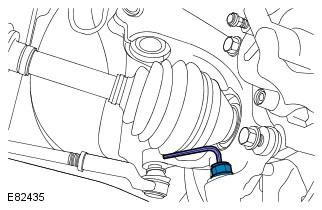
10. Special tool(s): 211-316
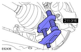
11. Remove the lower arm bolts and discard them.
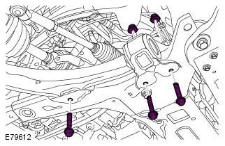
Installation
1.
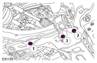
- Install the lower control arm.
- Tighten bolt 1. Tightening torque: Step 1: 140 Nm, Step 2: 45°
- Tighten bolt 2 with force. Tightening torque: 175 Nm
- Tighten bolt 3 with force. Tightening torque: 175 Nm
NOTE: Be sure to use new nuts and bolts.
2. Tightening torque: 100 Nm
CAUTION: Install a new lower control arm ball joint nut.
CAUTION: Do not allow the ball joint to rotate.
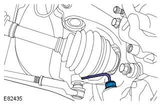
3. Partially insert the front axle shaft into the steering knuckle.
CAUTION: To avoid damage to the ball joint, do not allow the axle shaft to hang unsupported at one end.
4. Remove the load from the spring/shock absorber assembly and remove the special tool.
NOTE: This step requires the assistance of a second mechanic.
5. Install the new front axle bolt. Tightening torque: Step 1: 45 Nm, Step 2: 80°
Be sure to use a new bolt.
Make sure the brake hose is not kinked and is installed correctly.
6. Install the wheel. Refer to the procedure: Wheel and Tire (204-04 Wheels and Tires, Removal and Installation).
7. Lower the hood and secure the support posts in the clamps.
8. Install the collection chamber panel. Refer to procedure: Mixing Chamber (412-01 Climate Control, Removal and Installation).
Comments on this article