Contents: Removal ⇩ Installation ⇩
Special tool
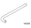 204-159 Lever, Wheel Knuckle 204-159 Lever, Wheel Knuckle | 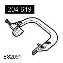 204-619 G-Clamp 204-619 G-Clamp |
Removal
1. Remove the mixing chamber panel. Refer to procedure: Mixing Chamber (412-01 Climate Control, Removal and Installation).
2. Release the hood support posts and secure the hood in a vertical position.
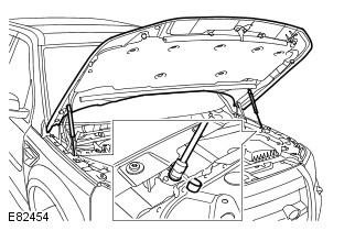
3. Raise and support the vehicle.
WARNING: Ensure that the vehicle is supported securely.
4. Remove the wheel and tire assembly. Refer to procedure: Wheel and Tire (204-04 Wheels and Tires, Removal and Installation).
5. Tightening torque: 60 Nm
WARNING: Use a new nut.
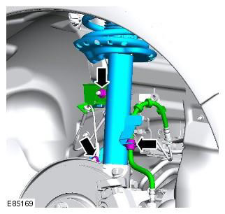
6. Tightening torque: 110 Nm
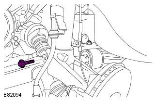
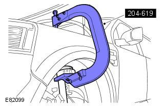
7. Compress the spring assembly with the shock absorber. Special tool(s): 204-619
NOTE: This step requires the assistance of a second mechanic.
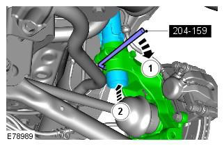
8. Disconnect the shock absorber from the knuckle assembly. Special tool(s): 204-159
9. Loosen the compression of the elastic element and shock absorber assembly and remove the tool.
NOTE: This step requires the assistance of a second mechanic.
(The article was copied from this resource www.LRman.ru)
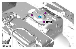
10. Remove the elastic element and shock absorber assembly. Tightening torque: 30 Nm
Installation
1. Install the elements back in place in reverse order.
Make sure the brake hose is not kinked and is installed correctly.
Nuts and bolts must be tightened when the vehicle is supported by the suspension.
NOTE: Clean the element from dirt and grease.
Comments on this article