Special tool
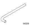 204-159 Lever, Wheel Knuckle 204-159 Lever, Wheel Knuckle | 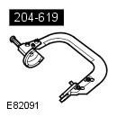 204-619 G-Clamp 204-619 G-Clamp | 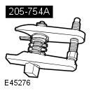 205-754A Splitter, Ball Joints 205-754A Splitter, Ball Joints |
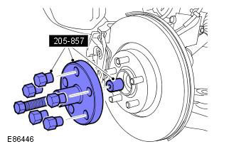
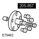 205-857 Remover, Halfshaft 205-857 Remover, Halfshaft | 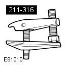 211-316 Separator, Ball Joint 211-316 Separator, Ball Joint |
Removing
NOTE: The description of the removal procedure in this manual may include installation steps.
1. Remove the mixing chamber panel. Refer to Procedure: Mixing Chamber (412-01 Climate control, Removal and installation).
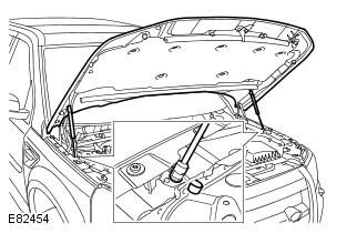
2. Release the hood support legs and lock the hood in a vertical position.
3. Raise and support the vehicle.
WARNING: Place secure stands under the vehicle.
4. Remove the wheel and tire assembly. Refer to procedure: Wheel and tire (204-04 Wheels and tires, Removal and installation).
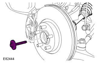
5. Tightening torque: Stage 1: 45 Nm. Stage 2: 60°
Discard the bolt. Do not use a pneumatic tool to tighten the bolt. Failure to follow this instruction may result in damage to this component.
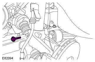
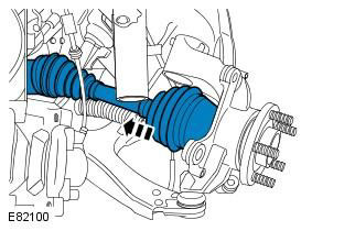
6. Disconnect the front half shaft from the steering knuckle, but do not remove completely. Special tool (s): 205-857
CAUTION: Do not use a hammer to separate the axle shaft from the hub assembly, failure to do so may result in damage to the axle shaft.
7. Tightening torque: 60 Nm
WARNING: Use a new nut.
CAUTION: Do not allow the ball joint to rotate.
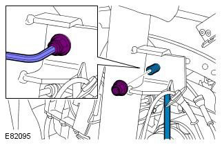
8. Tightening torque: 5 Nm
9. Tightening torque: 80 Nm
WARNING: Use a new tie rod end nut.
CAUTION: Do not allow the ball joint to rotate.
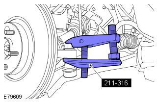
10. Special tool (s): 211-316
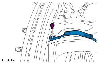
11. Tightening torque: 200 Nm
CAUTION: Do not stress the brake hose.
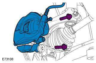
12. Tightening torque: 35 Nm
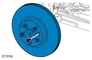
13. Tightening torque: 10 Nm
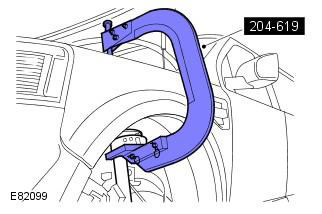
14. Special tool (s): 204-619
NOTE: This step requires the assistance of a second mechanic.
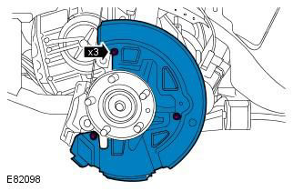
15. Tightening torque: 110 Nm
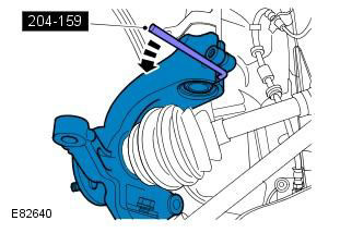
16. Special tool (s): 204-159
17. Warnings:
To avoid damage to the ball joint, do not allow the axle shaft to hang unsecured on one side.
Do not use a hammer to separate the axle shaft from the hub assembly, failure to do so may result in damage to the axle shaft.
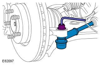
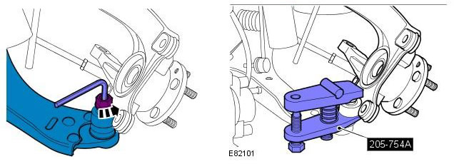
18. Special tool (s): 205-754A. Tightening torque: 100 Nm
WARNING: Install a new lower arm ball joint nut.
CAUTION: Do not allow the ball joint to rotate.
Installation
1. To install, follow the removal procedure in reverse order.
Make sure the brake hose is not kinked and is in the correct position.
Nuts and bolts need to be tightened while the vehicle is resting on the suspension.
Tighten the axle shaft bolt by hand.
NOTE: All contact surfaces of the elements must be clean.
Comments on this article