


Contents: Removal ⇩ Installation ⇩
Special tool
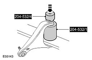
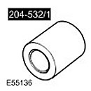 Upper Arm Bushing Receiver 204-532/1 Upper Arm Bushing Receiver 204-532/1 | 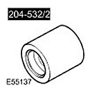 Upper Arm Bushing Remover 204-532/2 Upper Arm Bushing Remover 204-532/2 | 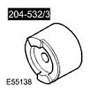 Device for mounting the front bushing of the upper arm 204-532/3 Device for mounting the front bushing of the upper arm 204-532/3 | 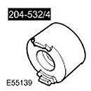 Upper Arm Rear Bushing Mounting Device 204-532/4 Upper Arm Rear Bushing Mounting Device 204-532/4 |
Removal
NOTE: Bushings must be replaced in pairs, left and right sides.
1.
CAUTION: Never work on a vehicle supported solely by a jack. Always support the vehicle securely.
Raise and support the vehicle.
2. Remove the front wheels and tires assemblies.
3. Remove the upper left control arm. For more information, refer to Upper Control Arm (60.35.01)
4. Remove the heat shield to gain access to the upper control arm bolts. Remove the nut. Remove the front bolt and loosen the rear bolt.
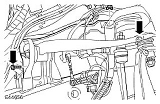
5. Loosen the upper control arm bolts.
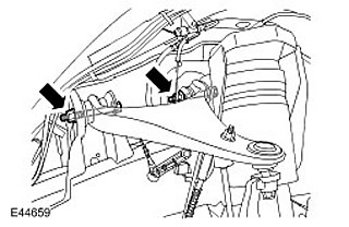
6. Disconnect the height sensor connector.
7.
CAUTION: To prevent the ball joint from turning, use the supplied Allen key.
Loosen the stabilizer bar strut nut. Discard the nut.
8.
CAUTION: To prevent the wheel knuckle from falling out and the inner axle joint from separating, support the wheel knuckle.
Loosen the upper control arm mounting nut.
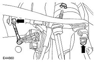
9. Using a special tool, disconnect the upper arm ball joint. Unscrew the nut and discard it.
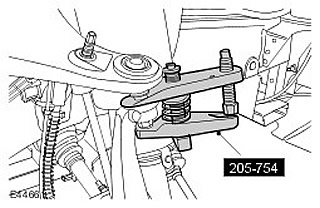
10. Disconnect the brake hose from the upper arm.
11. Disconnect the wheel speed sensor wire from the upper control arm.
12. Remove the upper right control arm.
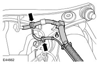
13. Remember the position of the bushing in relation to the upper arm.
14.
ATTENTION: To dismantle the bushing, it is necessary to remove its flanges.
Using a suitable tool, bend the flanges of the bushing.
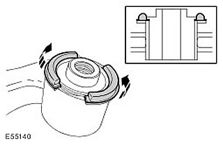
15. Use a hacksaw to separate the flange from the bushing without damaging the upper arm.
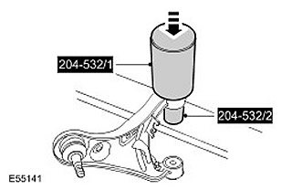
16. Using special tools, remove and discard the upper control arm bushings.
Installation
1.
CAUTION: Make sure the correct special tool is used to install the bushings to the correct depth.
Using special tools, install the rear bushings of the upper arm. Position the bushing so that the arrow on it points to the mark previously made on the upper arm.
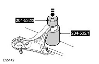
2. Using special tools, install the front bushings of the upper arm. Position the bushing so that the arrow on it points to the mark previously made on the upper arm.
3. Install the upper right control arm. Insert the bolts, but do not tighten them completely yet.
4. Secure the brake hose to the upper arm. Tighten the bolt. (tightening torque 23 Nm).
5. Secure the wheel speed sensor wire to the upper arm.
6. Attach the upper control arm to the wheel knuckle. Screw on a new nut and tighten it. (tightening torque 70 Nm).
7. Secure the stabilizer bar strut. Screw on a new nut and tighten. (tightening torque 115 Nm).
8. Attach the height sensor lever.
9. Adjust the height distance between the center of the axle shaft end and the edge of the fender trim panel to 466 mm.
10. Tighten the 2 upper control arm nuts and bolts (tightening torque 175 Nm).
11. Secure the heat shield.
12. Install the upper left control arm. For more information, refer to Upper Control Arm (60.35.01)
13. Install the front wheels. Tighten the wheel nuts. (tightening torque 140 Nm).
Comments on this article