Contents: Examination ⇩ To perform the adjustment ⇩
Before disconnecting the battery, make sure that all precautions specified for this procedure have been followed.
GENERAL INFORMATION, Precautions when working with electrical equipment.
Examination
1. Disconnect the negative cable from the battery.
2. Remove the fan with viscous coupling.
COOLING SYSTEM: Td6, REPAIR WORK, Viscous fan clutch.
3. Remove the valve cover with gasket.
TD6 ENGINE, REPAIR WORK, Valve cover gasket.
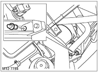
4. Unscrew the plug of the hole of the crankshaft TDC lock.
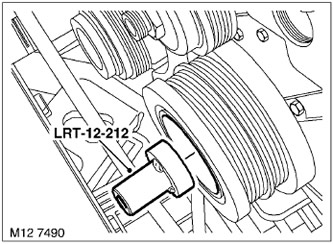
5. Using the LRT-12-212 tool installed on the crankshaft pulley, turn the crankshaft in the direction of normal rotation until the piston of the first cylinder is at TDC on the compression stroke.
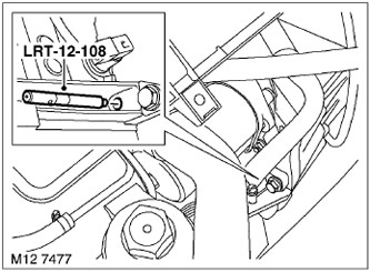
6. To fix the crankshaft in the TDC position of the first cylinder, install the LRT-12-108 device.
CAUTION: Do not rotate the engine against the normal direction of rotation.
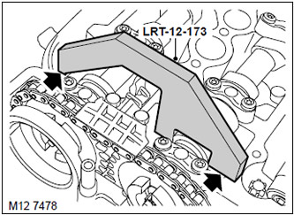
7. Install the LRT-12-173 tool onto the intake camshaft.
8. If the intake camshaft is in the correct position, the bearing surfaces of the LRT-12-173 tool will touch the valve cover recess plane on both sides.

9. Remove the LRT-12-173 tool from the intake camshaft and install it on the exhaust camshaft.
10. If the exhaust camshaft is in the correct position, the bearing surfaces of the LRT-12-173 will touch the valve cover recess plane on both sides.
To perform the adjustment
1. Loosen the clamp and remove the hose from the vacuum pump.
2. Remove and discard the two vacuum pump mounting bolts.
3. Remove the vacuum pump and discard the O-ring.
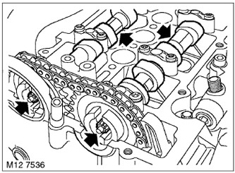
4. After securing the crankshaft with the LRT-12-108 tool and holding the camshafts with an open-end wrench by the hexagons, unscrew and dispose of the bolts securing the chain drive sprockets.
5. Using new bolts, tighten the sprockets until they rotate freely without end play.
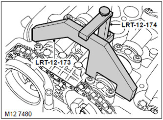
6. Install the LRT-12-174 tool onto the cylinder head.
7. Using the LRT-12-173 tool, set the intake camshaft to the correct position and tighten the LRT-12-174 tool mounting bolt.
8. Holding the exhaust camshaft with a hex key and using a torque sector, tighten the exhaust camshaft sprocket mounting bolt to 20 Nm and turn it another 35°.
9. Loosen the LRT-12-174 tool mounting bolt and remove the LRT-12-173 tool from the intake camshaft.
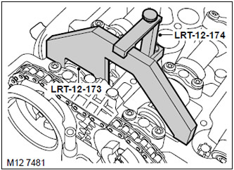
10. Using the LRT-12-173 tool, set the exhaust camshaft to the correct position and tighten the LRT-12-174 tool mounting bolt.
11. Holding the intake camshaft with a hex key and using a torque sector, tighten the intake camshaft sprocket mounting bolt to 20 Nm and turn it another 35°.
12. Remove fixtures LRT-12-174 and LRT-12-173.
13. Remove tool LRT-12-108 to release the crankshaft.
14. Using the LRT-12-212 tool installed on the crankshaft pulley, rotate the crankshaft two turns in the direction of normal rotation until the piston of the first cylinder is at TDC on the compression stroke.
15. To fix the crankshaft in the TDC position of the first cylinder, install the LRT-12-108 device.
CAUTION: Do not rotate the engine against the normal direction of rotation.
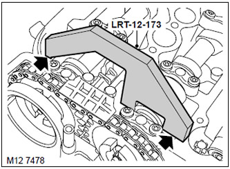
16. Install the LRT-12-173 tool onto the intake camshaft.
17. If the intake camshaft is in the correct position, the bearing surfaces of the LRT-12-173 tool will touch the valve cover recess plane on both sides.
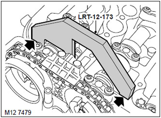
18. Remove the LRT-12-173 tool from the intake camshaft and install it on the exhaust camshaft.
19. If the exhaust camshaft is in the correct position, the bearing surfaces of the LRT-12-173 tool will touch the valve cover recess plane on both sides.
20. If necessary, the valve timing adjustment should be repeated.
21. Remove fixtures LRT-12-173 and LRT-12-108.
22. Screw in the plug of the crankshaft TDC locking hole.
23. Clean the mating surfaces on the vacuum pump and on the cylinder head.
24. Install a new O-ring on the vacuum pump.
25. Align the vacuum pump arm with the camshaft, install the vacuum pump and, using new bolts, secure it, tightening the bolts to a torque of 22 N·m.
26. Place the hose on the vacuum pump and tighten the clamp.
27. Install the valve cover with gasket.
TD6 ENGINE, REPAIR WORK, Valve cover gasket.
28. Install the fan with viscous coupling.
COOLING SYSTEM: Td6, REPAIR WORK, Viscous fan clutch.
29. Connect the negative cable to the battery.
Comments on this article