


Contents: Removal ⇩ Installation ⇩
Removal
1. Disconnect the ground wire from the battery.
For more information, refer to the chapter: Disconnecting and connecting the battery (414-01 Battery, Battery Mounting and Cables, General Procedures).
2. Remove the refrigerant from the air conditioning system.
For more information, refer to the chapter: Refrigerant Recovery, Evacuation and Charging of the Air Conditioning (A/C) System (412-00 Climate Control System - General Information, General Procedures).
3. Remove the engine control module (ECM).
For more information, refer to the chapter: Engine Control Module (ECM) (303-14 Electronic controls - Diesel engine ID4 2.4L, Removal and installation).
4.
CAUTION: Plug all openings. Use new caps.
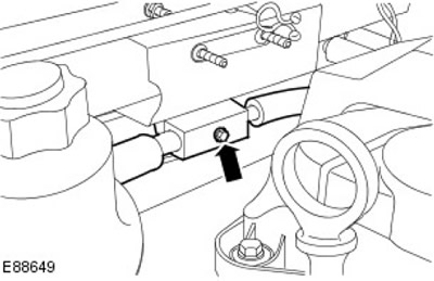
Release the thermostatic expansion valve manifold with the tube assembly.
- Remove the bolt.
- Remove and discard the O-rings.
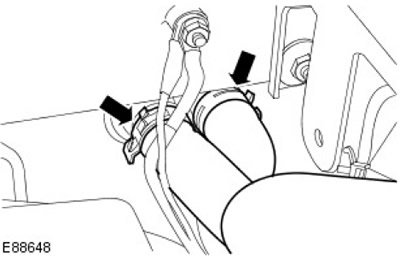
5. Disconnect the heater radiator hoses.
- Use a suitable clamp to secure the heater hoses.
- Release the two clamps.
6. Remove the control panel.
For more information, please refer to the chapter: Control Panel (501-12 Instrument panel and console, Removal and installation).
7.
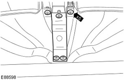
NOTE: Clamps should be discarded.
Remove the audio unit support bracket. Remove and discard the 5 clips.
8. Remove the left glass blower duct. Remove the clamp.
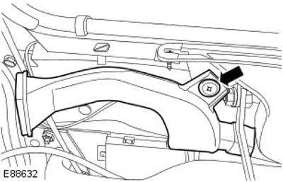
9. Release the left glass heating duct. Remove the screw.
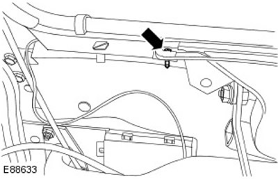
10. Remove the left glass heating duct. Remove the clamp.
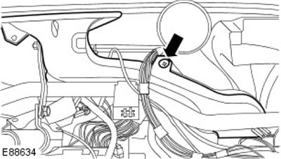
11. Remove the right glass blower duct. Remove the clamp.
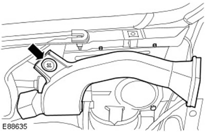
12. Release the right glass heating duct. Remove the screw.
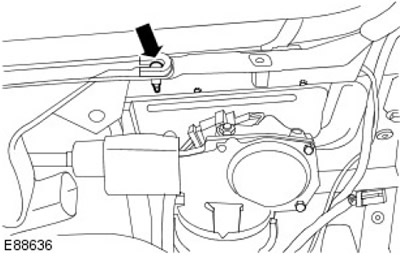
13. Remove the right air duct. Remove the clamp.
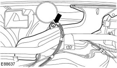
14. Remove the central deflector.
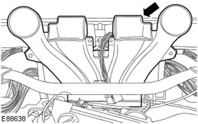
15. Remove the air intake duct. Remove the nut.
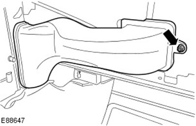
16. Disconnect the glass heating air duct flap control cable. Release the clamp.
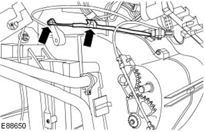
17. Disconnect the footwell heating air duct flap control cable. Release the clamp.
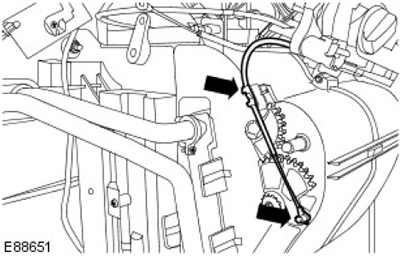
18. Remove the bushing from the partition.
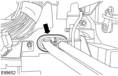
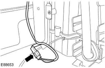
19. Disconnect the heated glass switch electrical connector.
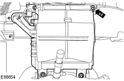
20. Remove the heater and evaporator radiator housing. Unscrew the 4 nuts.
Installation
1. Install the elements in place in the reverse order. Tighten (tightening torque 15 Nm).
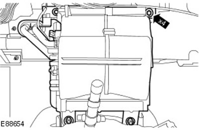
2. Tighten (tightening torque 8 Nm).
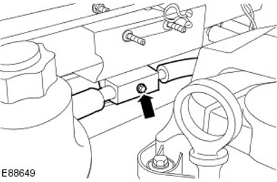
3. Connect the ground wire to the battery.
For more information, refer to the chapter: Connecting the Battery (414-01 Battery, Battery Mounting and Cables, General Procedures).
Comments on this article