


Special tool(s)
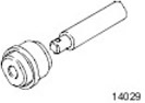 | Installation tool, outer bearing race/front wheel hub seal 204-087 |
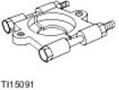 | Puller, Bearing/Gear 205-310 |
 | Mounting Bracket, Engine/Differential 205-329 |
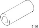 | Protection, axle shaft 205-332 |
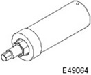 | Assembly Tool, Secondary Drive Flange Seal 308-604 |
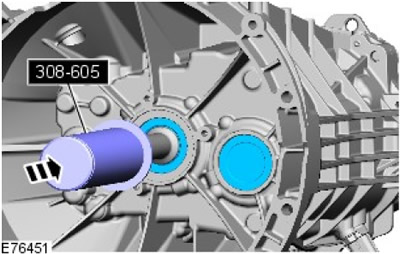
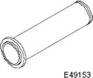 | Assembly tool, input shaft seal 308-605 |
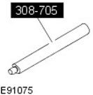 | Handle, Bearing Mounting Tool 308-705 |
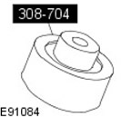 | Assembly tool, intermediate shaft bearing 308-704 |
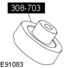 | Assembly tool, primary shaft bearing 308-703 |
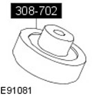 | Assembly tool, secondary shaft bearing 308-702 |
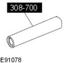 | Assembly tool, gear selector shaft seal 308-700 |
General equipment
- Clamps
- Hot air gun
- Hydraulic press
Materials
| Name | Specification |
| Transmission fluid | WSD-M2C200-C |
| High temperature grease | ESD-M1C220-A |
| Sealant | WSK-M2G348-A5 |
| Glue - Loctite 243 | WSK-M2G349-A7 |
Assembly
1.
NOTE: Before assembly, lubricate all synchronizer rings and needle bearings with clean gear oil.
2. Install the 4th gear and 3rd/4th gear synchronizer assembly onto the intermediate shaft.
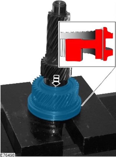
3. Install the 3rd/4th gear synchronizer snap ring assembly onto the intermediate shaft. Install a new snap ring.
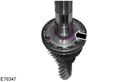
4. Using a special tool, install 6th gear on the intermediate shaft.
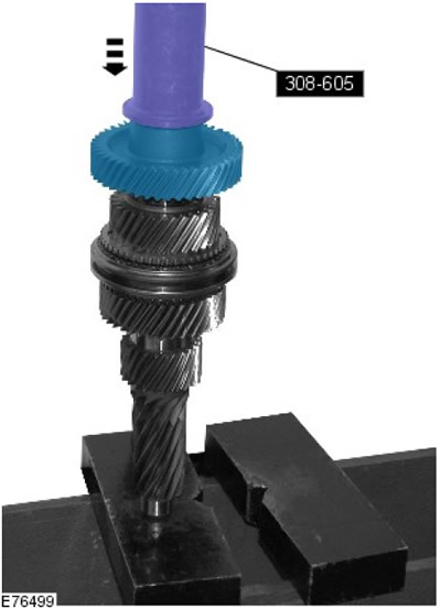
5. Using special tools, set 5th gear.
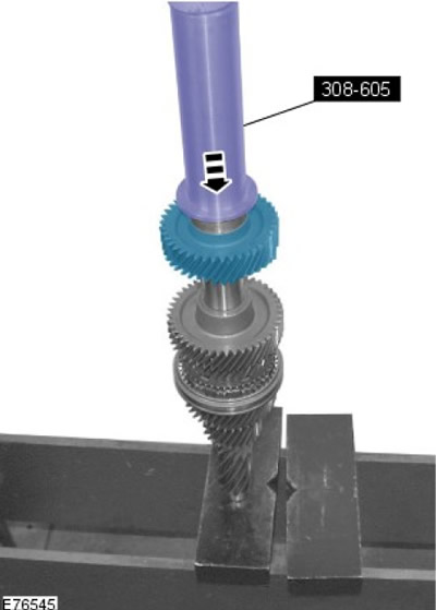
6. Using the special tools, install the 5th/6th gear synchronizer assembly onto the secondary shaft.
7.
WARNING: Use caution when using the fan heater. Failure to follow this instruction may result in injury.
NOTE: Heat the gearbox housing to approximately 100°C using a heat gun.
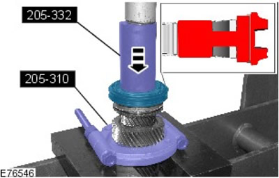
Using the special tool, install the outer race of the intermediate shaft bearing into the gearbox housing.
8.
WARNING: Use caution when using the fan heater. Failure to follow this instruction may result in injury.
NOTE: Heat the gearbox housing to approximately 100°C using a heat gun.
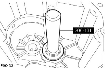
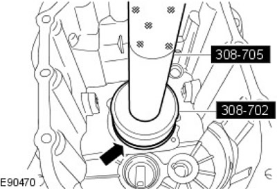
Using special tools, install the secondary shaft bearing.
(The original source of the article is the website: www.LRman.ru)
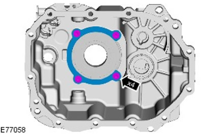
9. Install the secondary shaft locking plate. Tighten the bolts to 10 Nm.
10.
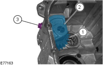
NOTE: Install the components in the positions marked during removal.
Install the units into the gearbox housing as follows.
- 1. Intermediate shaft roller bearing.
- 2. Reverse intermediate gear.
- 3. Fastening the reverse intermediate gear.
- 4. Tighten the bolt (tightening torque 27 Nm).
11.
WARNING: Use caution when using the fan heater. Failure to follow this instruction may result in injury.
NOTE: Heat the gearbox housing to approximately 100°C using a heat gun.
Using the special tool, install the intermediate shaft bearing.
12.
WARNING: Use caution when using the fan heater. Failure to follow this instruction may result in injury.
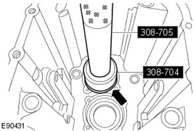
NOTE: Heat the gearbox housing to approximately 100°C using a heat gun.
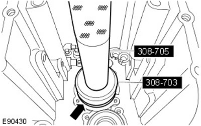
Using special tools, install the input shaft bearing.
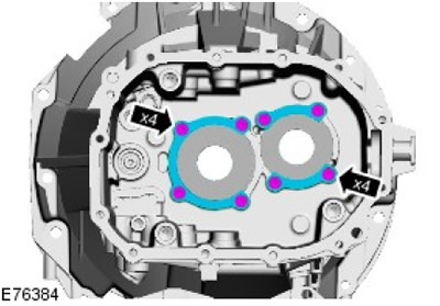
13. Install the bearing retaining plates. Tighten the bolts to 10 Nm.
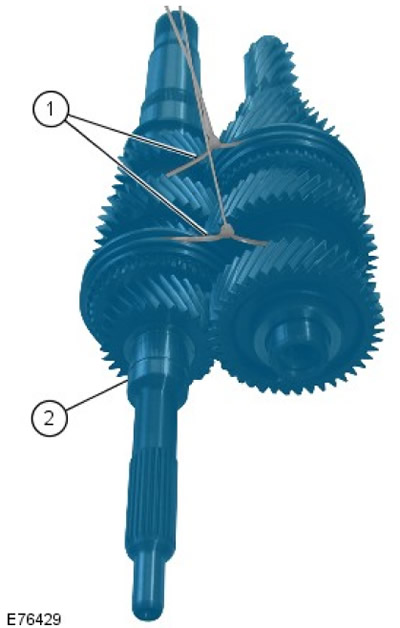
14. Connect the shafts together.
- 1. Install suitable clamps at the indicated points.
- 2. Make sure the input shaft has not come loose.
15.
WARNING: Use caution when using the fan heater. Failure to follow this instruction may result in injury.
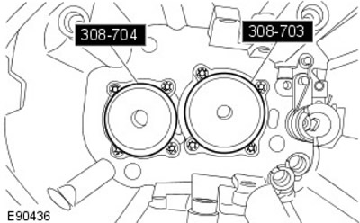
NOTE: Heat the special tools with a heat gun to approximately 100°C and transfer them to the bearings.
Using special tools, heat the middle bearing rings.
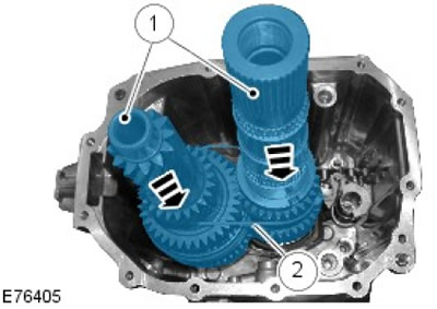
16. Install the secondary and intermediate shaft assemblies. Remove and discard the clamps.
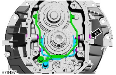
17. Install the 3rd/4th and 5th/6th gear selectors. Tighten the bolts to 37 Nm.
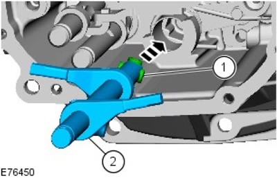
18. Install the main selector.
- 1. Apply grease to the bearings.grease
- 2. Install the main selector.
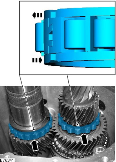
19. Install the center bearings.
20. Install the center bearing mounting plate. Tighten the bolts (tightening torque 24 Nm).
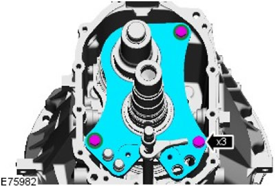
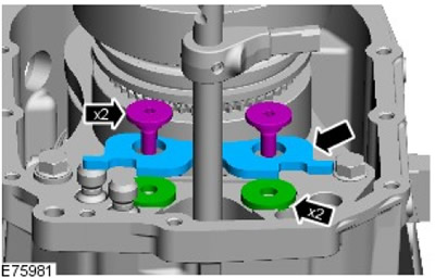
21. Install the gear selector shaft locking plate.
- Install the spacer bushings.
- Tighten the bolts (tightening torque 24 Nm).
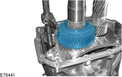
22. Install 2nd gear and bearing onto secondary shaft.
23. Using the special tools, install the 1st/2nd gear synchronizer assembly onto the secondary shaft.
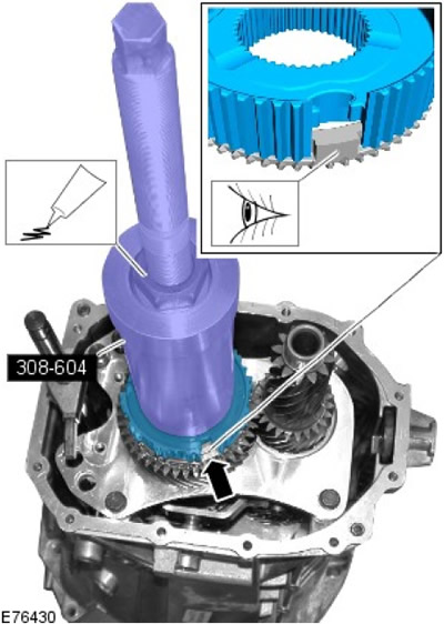
24. Install the 1st/2nd gear synchronizer retaining ring. Install a new snap ring.
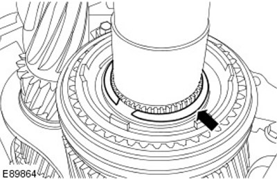
25. Install the 1st gear needle bearing.
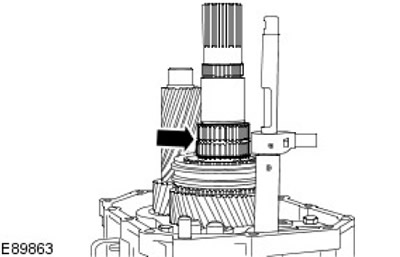
26. Set the transmission to 1st gear.
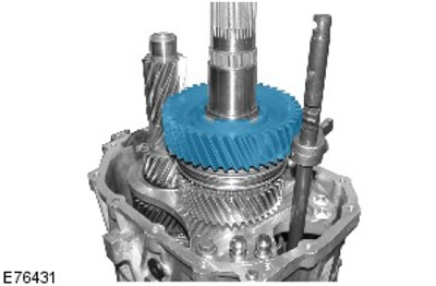
27.
WARNING: Use caution when using the fan heater. Failure to follow this instruction may result in injury.
NOTE: Heat the reverse gear bearing inner race to approximately 100°C using a heat gun.
Install the reverse gear bearing inner race.
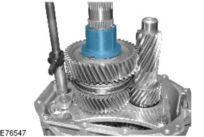
28. Install the reverse gear needle bearing.
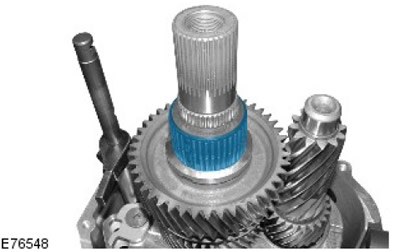
29. Install the reverse gear on the secondary shaft.
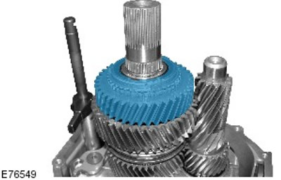
30. Using the special tool, install the reverse gear synchronizer onto the secondary shaft.
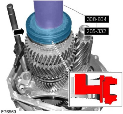
31. Install the 1st/2nd gear selector. Install a new pin.
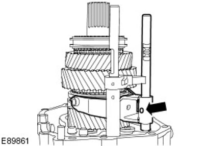
32. Install the reverse gear selector.
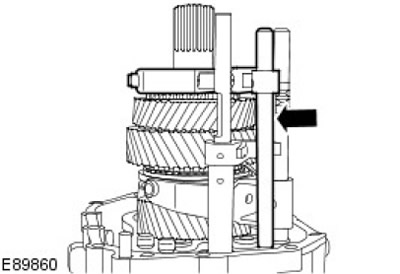
33. Select a gear.
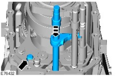
34. Install the magnet.
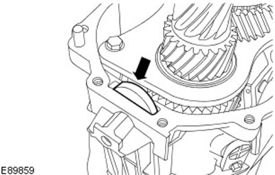
35.
WARNING: Use caution when using the fan heater. Failure to follow this instruction may result in injury.
NOTE: Heat the special tool with a heat gun to approximately 100°C and transfer it to the bearing.
Using a special tool, heat the inner ring of the bearing.
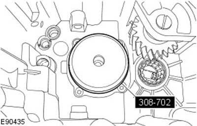
36. Install the gearbox housing.
- Apply sealant to the mating surfaces. sealant
- Install, but do not tighten, the transmission housing bolts.
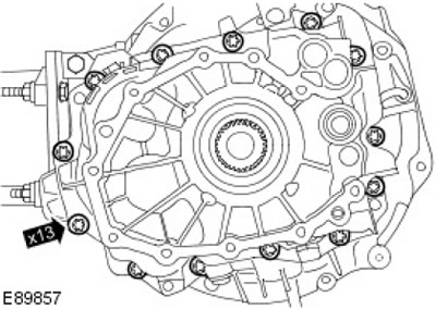
37. Install the reverse gear selector fork mounting bolts.
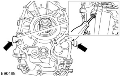
- Align the selector fork.
- Tighten it up (tightening torque 37 Nm).
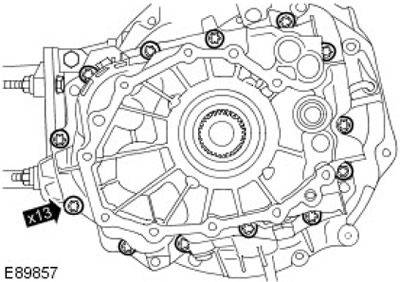
38. Tighten the transmission housing bolts in a crisscross pattern. Tighten (tightening torque 24 Nm).
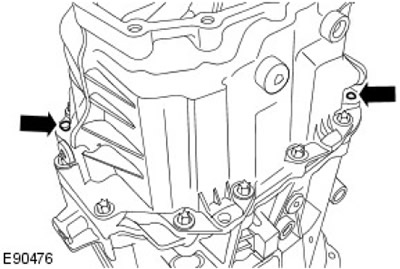
39. Reinstall the dowel pins.
40. Install new gear selector shaft stops.
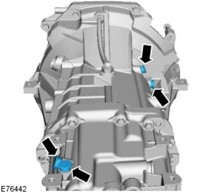
41. Move the main gear selector shaft to neutral position.
42. Install the new gear selector shaft stop.
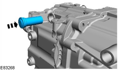
43. Using the special tools, install the main gear selector shaft seal.
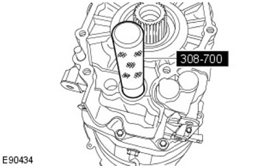
44. Install the gearbox secondary shaft seal.
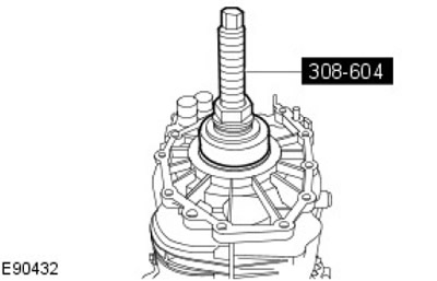
45.
WARNING: Use caution when using the fan heater. Failure to follow this instruction may result in injury.
NOTE: Using a heat gun, heat the gearbox output flange to approximately 100°C.
Using special tools, install the gearbox output flange.
- Tighten the bolt (tightening torque 210 Nm).
- Loosen the bolt.
- Apply thread locking compound. Glue
- Tighten the bolt (tightening torque 180 Nm).
46.
NOTE: Make sure the transmission is engaged.
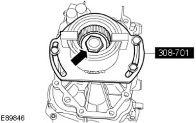
Install the intermediate shaft retaining bolt. Tighten (tightening torque 95 Nm).
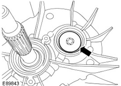
47. Install the input shaft retaining ring. Install a new snap ring.
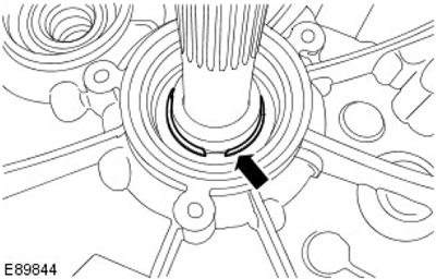
48. Turn the gearbox shafts and check the operation of all gears.
49. Using a suitable tool, check the torque of first gear in neutral by blocking the output flange. Maximum torque 1.2 Nm.
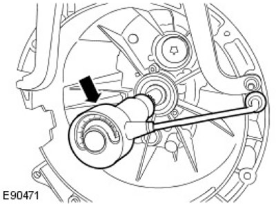
50. Using a special tool, install the primary and intermediate shaft seals of the gearbox.
51. Remove the gearbox from the stand.
52.
WARNING: Never work on a vehicle supported only by a jack. Always support the vehicle with special stands.
Raise the vehicle and place supports underneath it.
53. Install the gearbox in the block with the drive axle.
For more information, refer to the chapter: Gearbox (308-03 Manual transmission/gearbox in block with driving axle, Removal).
54. Fill the gearbox with oil.
For more information, refer to the chapter: Draining and Filling Transmission Fluid from the Transmission (308-03 Manual Transmission/Transaxle Transmission, General Procedures).
55. Connect the ground wire to the battery.
For more information, refer to the chapter: Connecting the Battery (414-01 Battery, Battery Mounting and Cables, General Procedures).
Comments on this article