


Special tool(s)
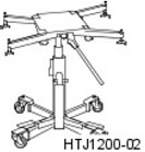 | Powertrain Jack Assembly HTJ1200-02 |
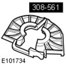 | Gear Selector Adjustment Tool 308-561 |
Installation
NOTE: If a new transmission is being installed, the shift lever mounting bolts must be installed to the transmission first to allow threads to be cut. Failure to follow this instruction will result in increased difficulty when installing the shift lever to the transmission.
1.
NOTE: Make sure the stud is inserted from left to right when viewed from the back of the transmission.
Install the gear shift fork.
- Install the pin.
- Tighten the nut to a torque of 12 Nm.
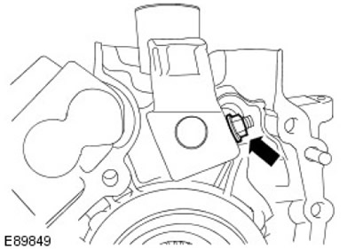
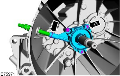
2. Install the clutch slave cylinder.
- Tighten the bolts (tightening torque 11 Nm).
- Install the connecting tube.
- Install the connecting tube clamp.
3. Install the reversing light switch. Tighten (tightening torque 20 Nm).
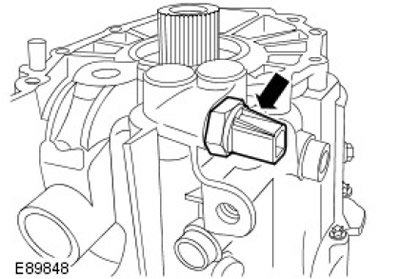
4. Install the seal.
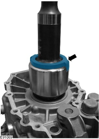
5.
NOTE: Apply anti-seize lubricant to the splines.
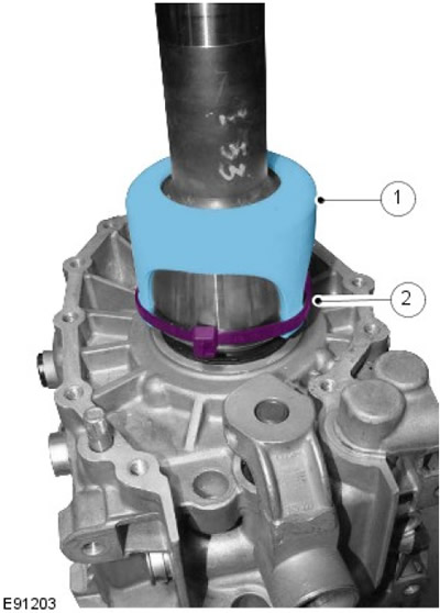
NOTE: Make sure the clamp is installed between the extension shaft seal cover tabs and that it is cut flush with the tabs.
Install the transmission extension shaft.
- Install the lid.
- Install the clamp.
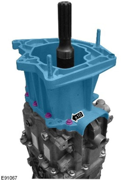
6. Install the gearbox console housing. Tighten the bolts (tightening torque 25 Nm).
7.
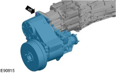
NOTE: Apply STC 50552 thread sealant to bolt threads.
With the help of an assistant, install the transfer case.
- Tighten the bolts (tightening torque 45 Nm).
- Tighten the nuts to 45 Nm.
8.
NOTE: This step should only be performed when installing a new transmission.
The article was copied from a resource (LRman.ru)
Screw in the gearshift housing mounting bolts to cut new threads. Remove the bolts.
9.
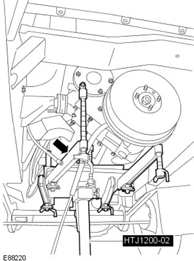
CAUTION: Use caution when mating the transmission to the clutch.
Install the gearbox and transfer case.
10.
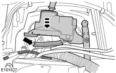
NOTE: Install the rubber gasket onto the shift lever housing before installation.
Install the gear shift housing.
11.
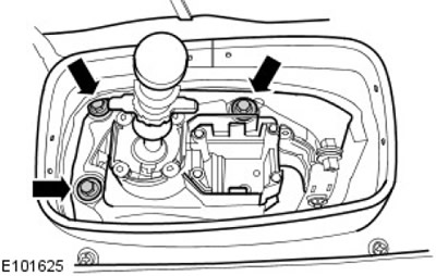
NOTE: From under the vehicle.
Install the three accessible gearshift housing mounting bolts and tighten finger tight only.
12. Attach the gearbox to the engine.
13. Screw in the front section crankcase mounting bolts. Tighten to 40 Nm.
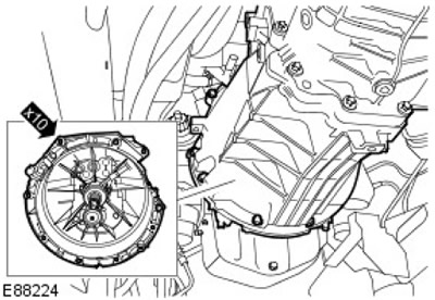
14. Install the right transfer case support bracket.
- Tighten the nut to 48 Nm.
- Tighten the bolts to 85 Nm.
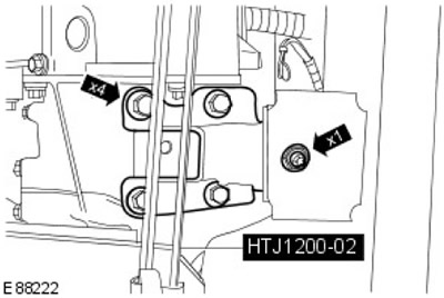
15. Install the left support and gearbox support bracket.
- Tighten the nut to 48 Nm.
- Tighten the bolts to 85 Nm.
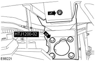
16. Remove special tool HTJ1200-02 from the gearbox and transfer case.
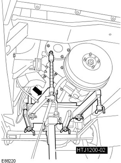
17. Connect the hose to the clutch slave cylinder.
- Remove the plugs from the holes.
- Install a new clutch slave cylinder hose O-ring.
- Install the clutch slave cylinder tube clamp.
18. Install and fully tighten the clutch slave cylinder hose support bracket nut and bolt.
- Remove the hose clamp from the clutch slave cylinder hose.
- Tighten the bolt to 25 Nm.
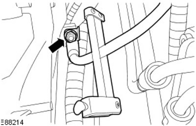
19. Secure the wiring harness to the gearbox.
20. Move the wiring harness and screw in the nut and bolt securing the transmission wiring harness bracket. Tighten to 47 Nm.
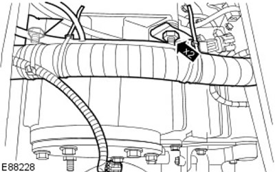
21. Install the transfer case breather pipe.
- Install new sealing washers on the transfer case breather pipe mounting bolt.
- Screw in the bolt.
- Tighten to 15 Nm.
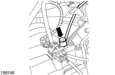
22. Connect the differential lock sensor electrical connector. Secure the electrical connector to the bracket.
23. Relocate and secure the high-low range sensing switch electrical connector to the transfer case. Secure the electrical connector to the bracket.
24. Screw in the bolt securing the right transfer case ground wires. Tighten to 12 Nm.
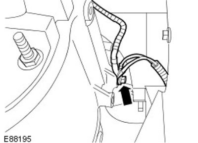
25. Screw on the nut securing the left transfer case ground wire. Tighten to 45 Nm.
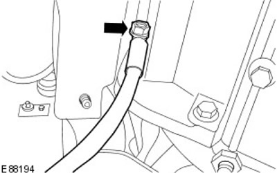
26. Connect the electrical connector of the electronic speedometer drive to the transfer case.
27. Install the parking brake assembly.
- Screw in four bolts.
- Tighten to 73 Nm.
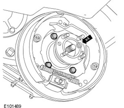
28. Install the brake drum. Screw in the screw.
29.
NOTE: Place in position marked during removal.
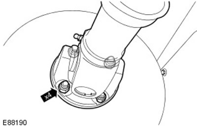
Move and secure the rear propeller shaft to the transfer case.
- Release the driveshaft from the chassis.
- Screw in the bolts securing the rear section of the propeller shaft to the transfer case.
- Tighten to 47 Nm.
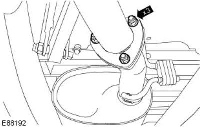
30. Install and secure the intermediate pipe and muffler.
- Install a new gasket.
- Screw the nuts securing the rear pipe with the muffler to the intermediate pipe.
- Tighten to 25 Nm.
31. Install the catalytic converter.
- Clean the mating surfaces of the catalytic converter.
- Install, but do not tighten, the two catalytic converter support bracket bolts.
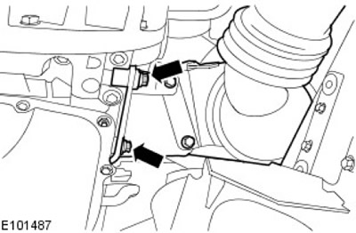
32. Secure the catalytic converter. Screw on, but do not tighten, the nuts securing the catalytic converter to the intermediate pipe.
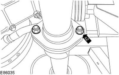
33. Lower the car.
34. Screw in four new catalytic converter mounting studs.
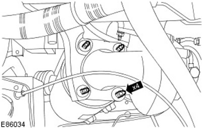
35. Screw on four new nuts. Tighten to 45 Nm.
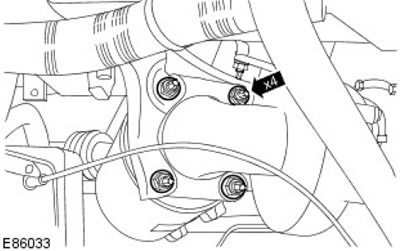
36. Install the turbocharger heat shield. Tighten to 10 Nm.
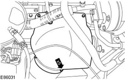
37. Close the hood.
38. Tighten to 30 Nm.
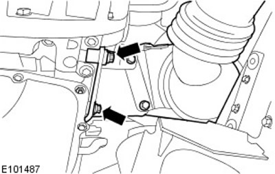
39. Tighten to 30 Nm.
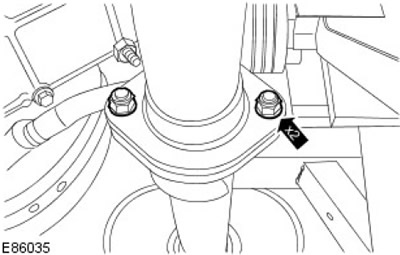
40. Install the front propeller shaft.
For more information, refer to the chapter: Front Propeller Shaft (205-01 Cardan shaft, Removal and installation).
41.
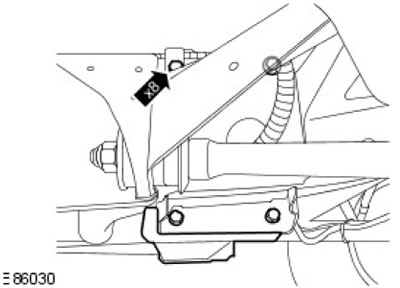
NOTE: Left side shown, right side similar.
Install the chassis crossmember. Tighten to 85 Nm.
42. Open the front door.
43. Connect the electrical connector of the reverse light switch.
44.
NOTE: Shift the transmission into third gear.
NOTE: Before installing the special tool, align the shift lever ball joint bushing and selector fork.
Install the gear shift lever. Install special tool 308561 to the gear shift lever.
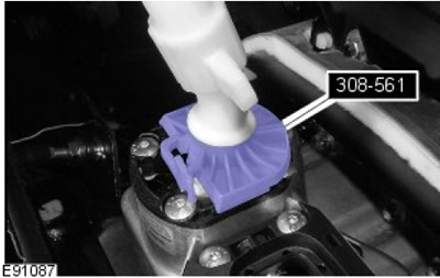
45. Tighten the four gearshift housing mounting bolts. Tighten to 25 Nm.
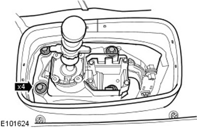
46. Remove special tool 308-561 from the gear shift lever.
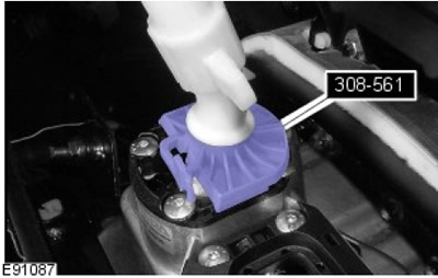
47. Screw on the new differential lock hinge nut. Tighten to 25 Nm.
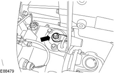
48. Install the high-low range selector lever to the transmission. Tighten to 7 Nm.
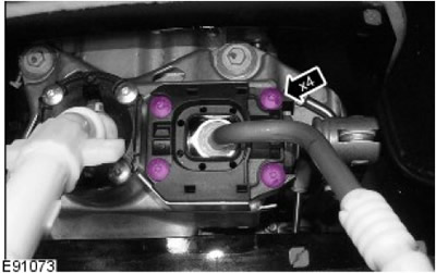
49. Install the foam padding.
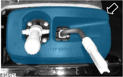
50. Install the upper gear shift lever.
51. Install the gear shift boot.
- Secure the gear shift boot to the transmission tunnel.
- Attach the shift lever boot to the high-low range selector lever.
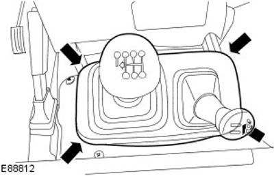
52. Install the carpet on the transmission cover panel.
53. Install the floor console assembly.
For more information, please refer to the chapter: Floor Console (501-12 Instrument panel and console, Removal and installation).
54. Connect the ground wire to the battery.
For more information, refer to the chapter: Disconnecting and connecting the battery (414-01 Battery, Battery Mounting and Cables, General Procedures).
55. Install the battery cover.
56. Install the front seat cushion assembly.
For more information, refer to the chapter: Front seat cushion (501-10 Seat, Removal and installation).
57. Raise the car on a lift.
58.
NOTE: Make sure the rod is fully seated on the ball joint and not on the foam washer.
Install the high-low range selector link ball joint to the transfer case.
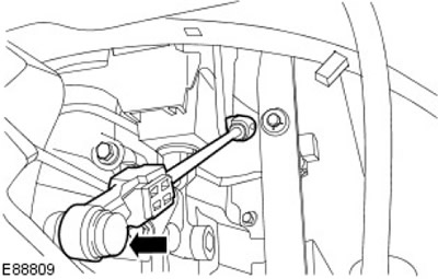
59. Bleed the air from the clutch hydraulic drive.
For more information, refer to the chapter: Bleeding the Clutch System (308-00 Manual Transmission/Transaxle and Clutch - General Information, General Procedures).
60. Lower the car.
Comments on this article