car logo Ford
car logo Volkswagen
car logo BMW
car logo Opel
car logo Audi
car logo Toyota
car logo Peugeot
English Русский
Български
Беларускі
Український
Српски
Hrvatski
Română
Polski
Slovenský
Magyar


Main
Freelander
Discovery
Range Rover
Defender
Contacts
Articles

1-2 and reverse gear selector shaft stoppers — removal and installation (Defender 2007+)

 
  • Main
  • Defender
  • Defender 2007+
  • Power unit
  • Mechanical gearbox
  • 1-2 and reverse gear selector shaft stoppers — removal and installation
 
        0  
Contents: Removal ⇩ Installation ⇩

Special tool(s)
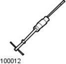

Hammer with movable striker 100-012
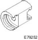
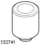
Puller, stopper 308-657
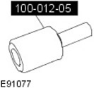
Impact Puller Adapter 100-012-05
Seal Puller 308-615

Removal


1. Remove the gear shift lever.

For more information, refer to the chapter: Gear Shift Lever (308-06 External controls for manual transmission in block with drive axle/gearbox - Diesel engine ID4 2.4L, Removal and installation).

2.
NOTE: Selector shaft stop designation.


Letter A represents the old selector shaft stop. Letter B represents the new selector shaft stop.
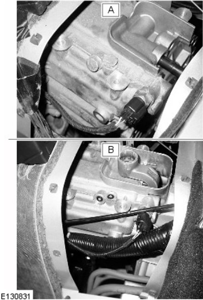
Letter A represents the old selector shaft stop. Letter B represents the new selector shaft stop.


3.
NOTE: Selector shaft stop symbol


Letter A represents the old selector shaft stop. Letter B represents the new selector shaft stop.
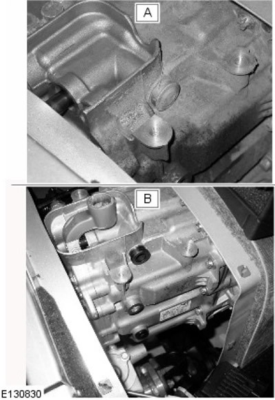
Letter A represents the old selector shaft stop. Letter B represents the new selector shaft stop.


4.
CAUTION: Make sure the surface surrounding the element is clean.


Using special tools, remove the selector shaft stopper.
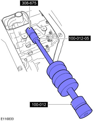
Using special tools, remove the selector shaft stopper.


5.
CAUTION: Make sure the surface surrounding the element is clean.


NOTE: If the selector shaft stoppers are of the new type as shown in the illustration, then to remove the stopper it will be necessary to drill a 5.5 mm diameter hole in the center of the stopper to a depth of approximately 3 mm to perforate the stopper housing. Then, using tool 308615, insert an M6 bolt into the stopper and use the appropriate special tool to remove the stopper.


NOTE: The older design stops shown in the illustration do not require drilling. Use the special tool shown in the illustration to remove the stop.


Using special tools, remove the selector shaft stopper.
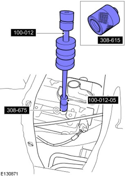
Using special tools, remove the selector shaft stopper.


6.
CAUTION: Make sure the surface surrounding the element is clean.


Using the appropriate special tools, remove the selector shaft stop.
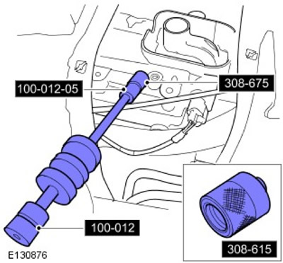
Using the appropriate special tools, remove the selector shaft stop.


7. After removing the 1st, 2nd and reverse gear stoppers from the selector rack, the shafts should be centered in the neutral position as shown in the figure. To do this, look into the holes from under the stoppers in the casting.
  • The shafts can be centred by carefully moving the selector to the middle position using a suitable flat-blade screwdriver.
  • After centering the shafts, check the ability to engage 3rd and 4th gears and the lateral movement of the lever.
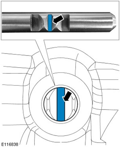
After centering the shafts, check the ability to engage 3rd and 4th gears and the lateral movement…


Installation


1.
CAUTION: New selector shaft stops must be installed flush with the transmission housing.


Using suitable tools, install the selector shaft stops.
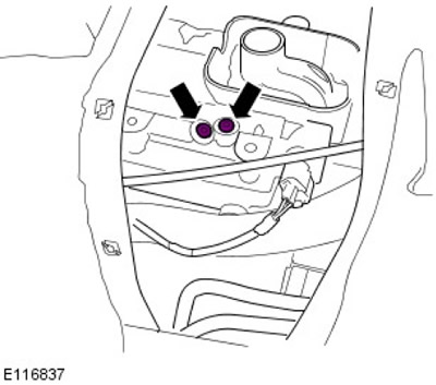
Using suitable tools, install the selector shaft stops.


2.
CAUTION: Make sure the component is completely seated in the crankcase.


Using suitable tools, install the selector shaft stop.
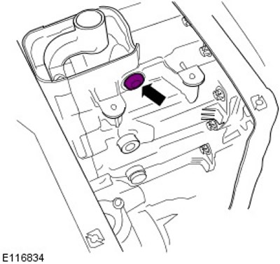
Using suitable tools, install the selector shaft stop.


3. Install the gear shift lever.

For more information, refer to the chapter: Gear Shift Lever (308-06 External controls for manual transmission in block with drive axle/gearbox - Diesel engine ID4 2.4L, Removal and installation).


This article is available at russian, bulgarian, belarusian, ukrainian, serbian, croatian, romanian, polish, slovak, hungarian
Article review: Saveliy Ushakov


Previous articles
Manual Transmission Specifications
Description and operating principle of a manual gearbox
Removal a manual gearbox
Installation of a manual gearbox
Disassembling a manual gearbox
Assembly of a manual gearbox
Synchronizers — disassembly

Current article
1-2 and reverse gear selector shaft stoppers — removal and installation

Next articles
Gear shift control shaft seal
Primary shaft seal — removal and installation
Selector shaft locks — removal and installation
Output shaft seal — removal and installation
Gear Shift Lever — Removal and Installation


Similar articles from Land Rover repair manuals:
• Gear selector knob Freelander 2 (2006-2014)
• Gear Selector Rod Seal PG1 Freelander 1 (1997-2006)
• Stoppers devices Discovery 3 (2004-2009)
• Replacing the rocker arm shaft Discovery 1 (1989-1998)
• Gear selector shaft seal Range Rover 3 (2001-2012)

Comments on this article


No comments yet


How much will 13 + 35 =


Defender 2007+ 
  • General information
  • Maintenance
  • Identification codes
  • Power unit
  • Diesel engine ID4 2.4L
  • Engine inspection
  • Engine cooling
  • Fuel supply
  • Fuel tank
  • Exhaust system
  • Accessory drive
  • Air filtration
  • Electronic parts
  • Mechanical gearbox
  • Transfer case
  • Clutch
  • Chassis
  • Car suspension
  • Wheels and tires
  • Steering
  • Steering column
  • Brake system
  • Front drive axle
  • Rear drive axle
  • Cardan shaft
  • Body and coating
  • Interior trim
  • Instrument panel and console
  • Exterior finish
  • Lockable body parts
  • Handles, locks, latches
  • Glass, frames and mechanisms
  • Windshield wipers and washers
  • Seats
  • Electrical equipment
  • Battery
  • Generator and regulator
  • Lighting and headlights
  • Winch
  • Heating and ventilation
  • Instrument panel
  • Other electronics


LRman.ru © 2013-2026 | Mobile version | Free Lander | Discovery | Range Rover | Defender | Contacts | | Sitemap |
Car repair and service instructions Land Rover: Freelander, Discovery, Range Rover, Defender
We use cookies to make pages load faster and provide a more user-friendly experience 🍪