Contents: Arrangement of elements ⇩ Review ⇩ Technical data ⇩ Primary shaft ⇩ Intermediate shaft ⇩ Secondary shaft ⇩ Triple synchronizer assembly ⇩ Synchronizer assembly ⇩ Reverse intermediate gear ⇩
Arrangement of elements
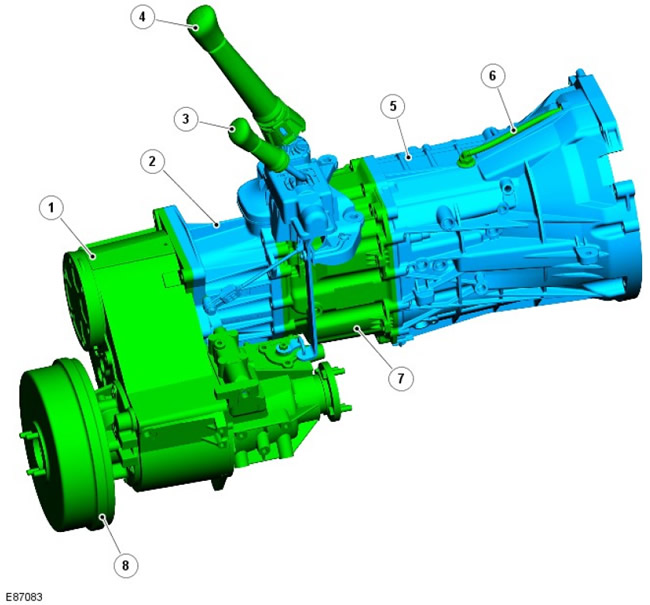
| Pos. | Spare part number | Name |
| 1 | - | Transfer case assembly |
| 2 | - | Gearbox housing extension |
| 3 | - | Transfer case selector lever |
| 4 | - | Gear selector lever |
| 5 | - | Gearbox front housing |
| 6 | - | Ventilation duct |
| 7 | - | Gearbox housing |
| 8 | - | Gearbox parking brake |
Review
The MT82 manual transmission has six forward gears and a reverse gear. It is mounted on the longitudinal axis of the car and its maximum torque is 360 Nm. The cast aluminum gearbox housing is bolted to the transfer case via a cast aluminum extension.
The 6th gear ratio was selected to improve fuel economy and provide comfort when driving fast. Optimum gear shifting ensures economical fuel consumption and efficient use of engine torque. The six-speed transmission provides a wide range of gear selection for improved economy and controllability (for example, when maneuvering at low speed or when driving with a trailer).
The name "MT82" reflects the distance between the two shafts in the gearbox:
- M - mechanical
- T - gearbox
- 82 - distance between two shafts in mm
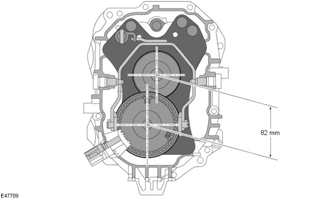
The transmission is filled for life and no level check is required during servicing unless a leak is found.
Technical data
|
Input torque |
Gear ratios |
Dry weight |
Refueling oils |
Specification oils |
||||||
|
1st |
2nd |
3rd |
4th |
5th |
6th |
Back |
||||
|
360Nm |
5,441 |
2,840 |
1,721 |
1,223 |
1,00 |
0,742 |
4,935 |
50,8 kg |
2.4L |
WSD-M2C200-C |
In 5th gear, the input and output shafts are directly connected to each other. In this case, the gear ratio is 1:1.
Model plate
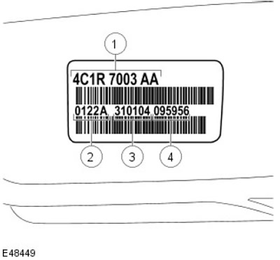
| Pos. | Spare part number | Name |
| 1 | - | Spare part number |
| 2 | - | Place of manufacture (Halewood) |
| 3 | - | Date of manufacture of the vehicle |
| 4 | - | Production time |
The identification plate is located on the right side of the gearbox in the area of the output flange for mounting the propeller shaft.
It is intended solely for the identification of the gearbox. All spare parts orders are subsequently made using the vehicle identification number (VIN).
Primary shaft
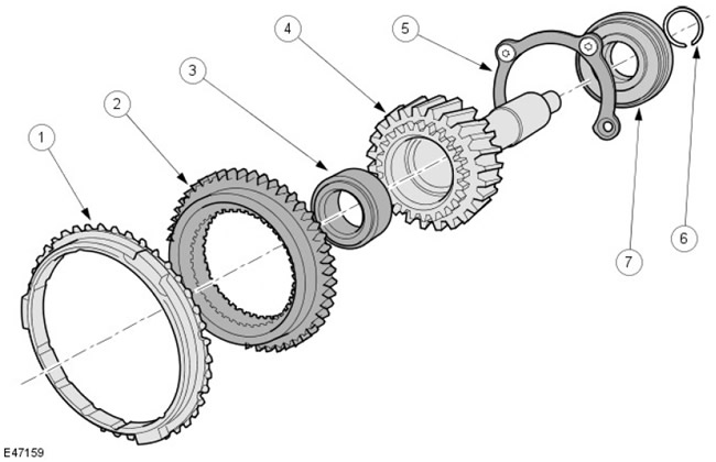
| Pos. | Spare part number | Name |
| 1 | - | 5th gear synchronizer retaining ring |
| 2 | - | 5th gear synchronizer ring gear |
| 3 | - | Secondary shaft guide bearing |
| 4 | - | Input shaft |
| 5 | - | Bearing retainer plate |
| 6 | - | Ball Bearing Retaining Ring |
| 7 | - | Primary shaft ball bearing |
The primary shaft is movably connected to the secondary shaft via a guide bearing (3). To absorb axial forces, the primary shaft ball bearing (7) has additional protection.
All components of the primary shaft can be serviced separately.
Intermediate shaft
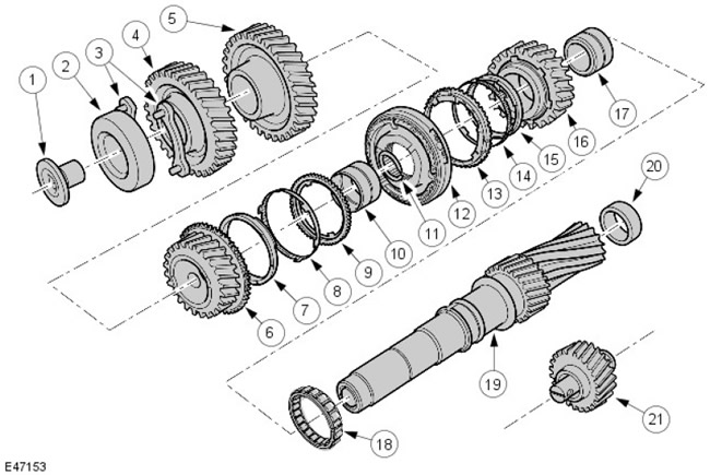
| Pos. | Spare part number | Name |
| 1 | - | Mounting bolt |
| 2 | - | Intermediate shaft ball bearing |
| 3 | - | Bearing retainer plate |
| 4 | - | Intermediate shaft drive gear |
| 5 | - | 6th gear driven gear |
| 6 | - | Third gear before achi |
| 7 | - | 3rd gear synchronizer cone |
| 8 | - | Inner synchronizer ring |
| 9 | - | 3rd gear synchronizer outer ring |
| 10 | - | Needle roller bearing |
| 11 | - | Retaining ring |
| 12 | - | Third and fourth gear synchronizer clutch assembly |
| 13 | - | 4th gear synchronizer outer ring |
| 14 | - | Inner synchronizer ring |
| 15 | - | 4th gear synchronizer cone |
| 16 | - | 4th gear pinion |
| 17 | - | Needle roller bearing |
| 18 | - | Intermediate shaft central bearing |
| 19 | - | Intermediate shaft |
| 20 | - | Intermediate shaft roller bearing |
| 21 | - | Reverse intermediate gear |
The intermediate shaft transmits torque from the primary shaft to the secondary shaft. The shaft contains the driving and driven gears, as well as the 3rd/4th gear synchronizer clutch. The 1st and 2nd gears and the reverse gear are non-removable.
The intermediate shaft drive and driven gears can be replaced individually. Improved manufacturing tolerances eliminate the need to replace pairs of gears.
The intermediate shaft is a single piece. To prevent axial movement of the shaft, it is additionally secured with a bolt (1) and a bearing lock plate (3).
The direction of rotation of the secondary shaft is changed using the intermediate reverse gear gear (21).
Secondary shaft
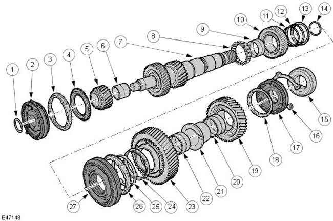
| Pos. | Spare part number | Name |
| 1 | - | Retaining ring |
| 2 | - | 5th/6th gear synchronizer clutch |
| 3 | - | 6th gear synchronizer retaining ring |
| 4 | - | 6th gear synchronizer ring gear |
| 5 | - | 6th gear pinion |
| 6 | - | Needle roller bearing |
| 7 | - | Output shaft |
| 8 | - | Secondary shaft intermediate bearing |
| 9 | - | Needle roller bearing |
| 10 | - | Leading gear 2nd gear |
| 11 | - | 2nd gear synchronizer cone |
| 12 | - | Inner synchronizer ring |
| 13 | - | 2nd gear synchronizer outer ring |
| 14 | - | Retaining ring |
| 15 | - | Secondary shaft ball bearing |
| 16 | - | Bearing retainer plate |
| 17 | - | Reverse gear synchronizer clutch |
| 18 | - | Reverse gear synchronizer retaining ring |
| 19 | - | Reverse gear pinion |
| 20 | - | Needle roller bearing |
| 21 | - | Inner ring of needle roller bearing |
| 22 | - | Needle roller bearing |
| 23 | - | The leading gear of the first gear |
| 24 | - | 1st gear synchronizer cone |
| 25 | - | Inner synchronizer ring 1st gear |
| 26 | - | 1st gear synchronizer outer ring |
| 27 | - | 1st/2nd gear synchronizer clutch |
The rotation of the secondary shaft is transmitted through the output flange to the extension shaft connected to the transfer case. The 1st, 2nd and 6th gears, as well as the reverse gear gear, are located on the secondary shaft. The 3rd and 4th gears on the secondary shaft are non-removable.
By analogy with the primary shaft, the 6th gear drive pinion has a mounted synchronizer ring gear (4). It ensures the transmission of torque when 6th gear is engaged.
The secondary shaft drive and driven gears can be replaced separately.
Triple synchronizer assembly
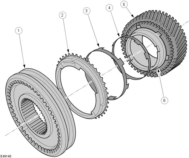
| Pos. | Spare part number | Name |
| 1 | - | 1st/2nd gear synchronizer clutch |
| 2 | - | Outer synchronizer ring |
| 3 | - | Inner synchronizer ring |
| 4 | - | Synchronizer cone |
| 5 | - | Driven gear |
| 6 | - | Surface of a cone |
The synchronizer unit has three friction surfaces. Due to the additional conical surface (6), the total friction surface during triple synchronization increases significantly. This allows for a reduction in the required shift force to 1st and 2nd gear.
Since the conical surface is part of the pinion gear, no additional synchronizer ring is required.
Synchronizer assembly
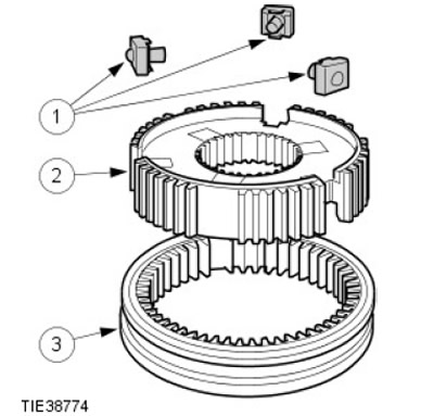
| Pos. | Spare part number | Name |
| 1 | - | Carriage assembly |
| 2 | - | Synchronizer hub |
| 3 | - | Sliding synchronizer clutch |
The pressure springs and the carriage locking balls are combined into one unit.
Reverse intermediate gear
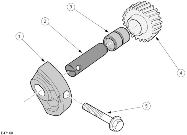
| Pos. | Spare part number | Name |
| 1 | - | Support bracket |
| 2 | - | Reverse gear intermediate gear shaft |
| 3 | - | Needle roller bearing |
| 4 | - | Reverse intermediate gear |
| 5 | - | Reverse gear support bracket mounting bolt |
The intermediate reverse gear pinion is used to change the direction of rotation of the secondary shaft. The intermediate reverse gear pinion is equipped with a needle roller bearing mounted on the intermediate gear axle. The axle is secured in the support bracket (1) and the mating hole in the gearbox housing.
To absorb radial forces, the intermediate gear of the reverse gear is additionally located on the support bracket.
If the reverse gear intermediate gear can be replaced separately.
Comments on this article