Special tool (s)
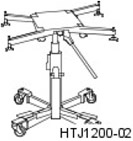 | Power unit jack assembly HTJ1200-02 |
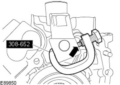
 | Puller, slider 308-652 |
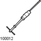 | Impact puller 100-012 |
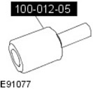 | Hammer adapter 100-012-05 |
Removing
1. Open the front door.
2. Remove the front seat cushion assembly.
For more information, see chapter: Front seat cushion (501-10 Seat, Removal and installation).
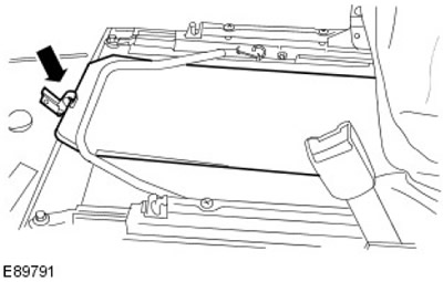
3. Remove the battery cover. Release the clamp.
4. Disconnect the wire "masses" from the battery.
For more information, see the chapter: Disconnecting and connecting the battery (414-01 Battery, Battery Mount and Wires, General Procedures).
5. Remove the center floor console.
For more information, see the chapter: Floor Console (501-12 Instrument panel and console, Removal and installation).
6. Remove the carpet from the transmission cover panel.
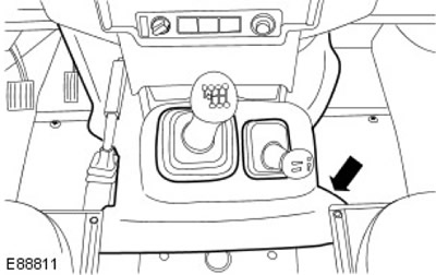
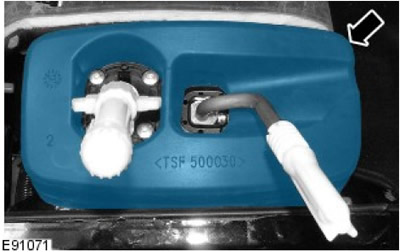
7. Release a cover of the lever of a gear change.
- Release the shift lever boot from the transmission tunnel.
- Release the shift lever boot from the clips on the high-low range select lever.
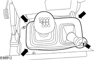
8.
WARNING: The shift knob releases abruptly, so turn to the side when removing. Failure to follow this instruction may result in injury.
Remove the upper shift lever.
9. Remove a cover of the lever of a gear change.
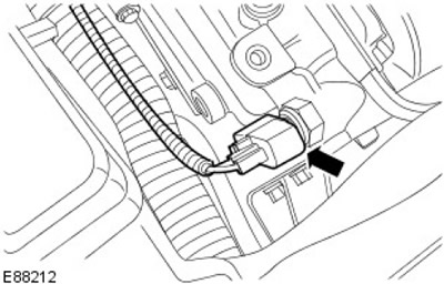
10. Disconnect an electric socket of the switch of a lantern of a backing.
11. Open the hood for access.
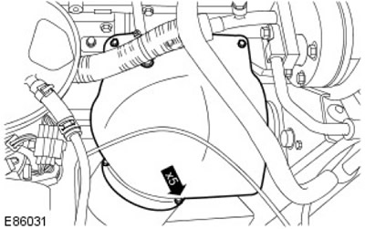
12. Remove the turbocharger heat shield. Turn out five bolts.
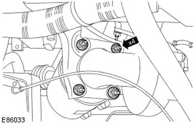
13. Turn out four hairpins of fastening of catalytic converter.
14.
WARNING: It is forbidden to carry out work on a vehicle standing on only one jack. Always support the vehicle with jack stands.
Raise the car and place stands under it.
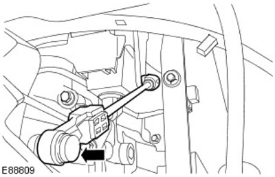
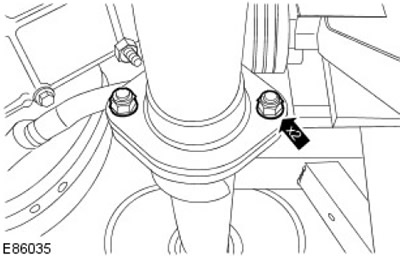
15. Disengage the high-low selector linkage ball joint from the transfer case.
16. Lower the car.
17. Open the front door.
18. Remove the foam padding around the shift levers.
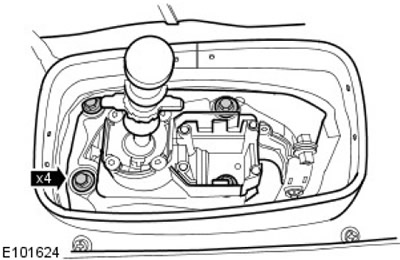
19. Turn out four bolts of fastening of the lever of a high-low range.
20. Remove the high-low range select lever.
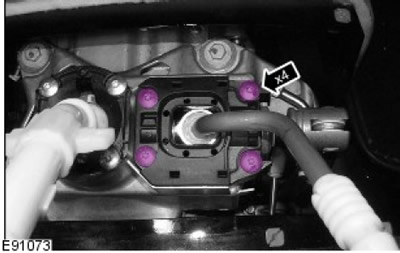
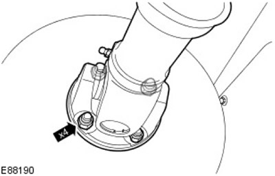
21. Turn out four bolts of fastening of the case of a choice of transfers.
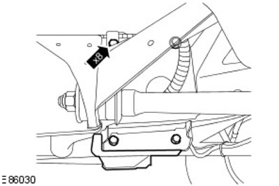
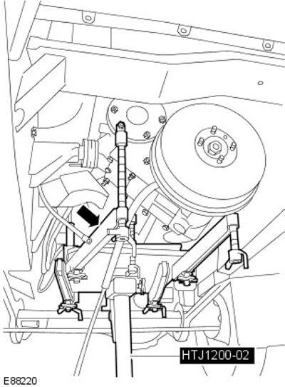
22.
NOTE: Left side shown, right side similar.
Remove the chassis cross member. Remove 8 bolts.
23. Remove the front propeller shaft.
For more information, see chapter: Front propeller shaft (205-01 Cardan shaft, Removal and installation).
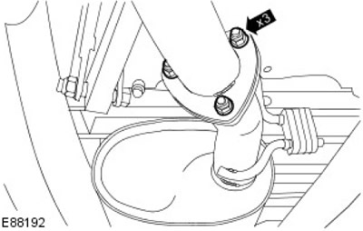
24. Turn away two nuts of fastening of catalytic converter to an intermediate pipe.
25. Turn out two bolts of fastening of a basic arm of catalytic converter.
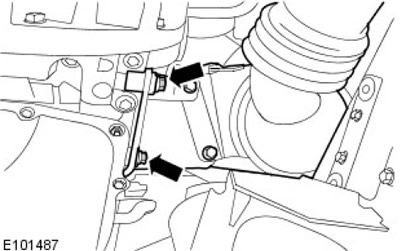
26. Remove the catalytic converter.
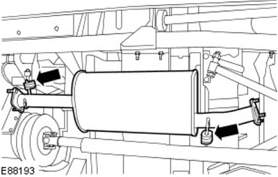
27. Turn away nuts of fastening of a back pipe with the muffler to an intermediate pipe.
28. Remove the intermediate pipe and muffler.
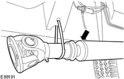
29. Move the rear section of the driveshaft.
- Mark the position of the driveshaft relative to the drive gear flange.
- Turn out nuts of fastening of back section of the cardan shaft to a distributing box.
30. Using a suitable clamp, secure the rear section of the driveshaft to the chassis.
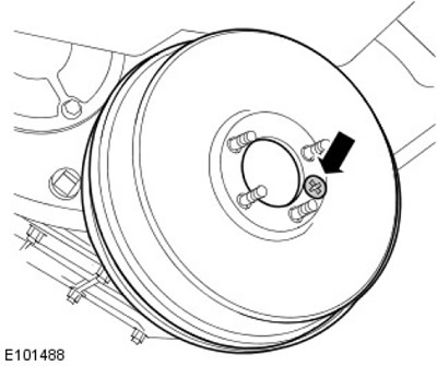
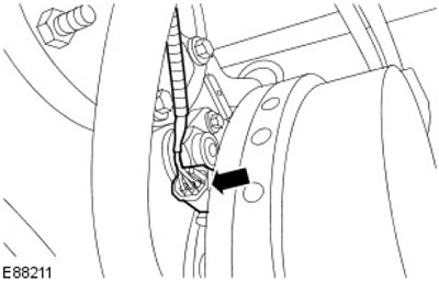
31. Remove the parking brake drum. Remove the screw.
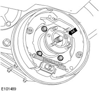
32. Remove parking brake assembly and tie aside.
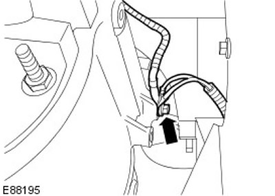
33. Disconnect the electrical connector for the electronic speedometer drive on the transfer case.
34. Remove the nut and disconnect the left ground wire from the transfer case.

35. Turn out a bolt of fastening of the right wires of grounding from a distributing box.
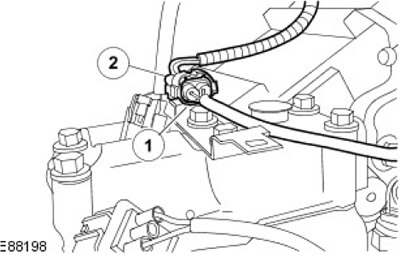
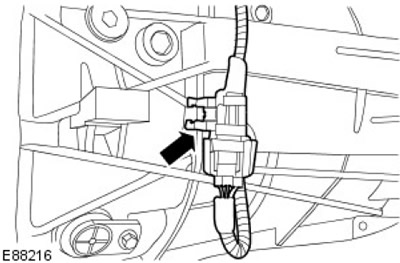
36. Move the high-low range detection switch electrical connector away from the transfer case. Disconnect the high-low detection switch electrical connector.
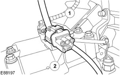
37. Disconnect the differential lock sensor electrical connector. Release the electrical connector from the bracket.
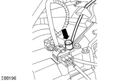
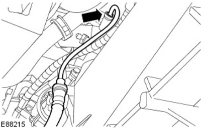
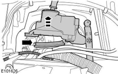
38. Release the breather pipe from the transfer case.
- Turn out a bolt.
- Remove and discard two sealing washers.
39. Turn away a nut and turn out a bolt of fastening of an arm of a plait of electroconducting of a transmission and move a plait of electroconducting.
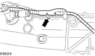
40. Release the electrical connector and transmission harness bracket from the clip on the right side of the transmission.
41. Remove the clip securing the transmission wiring harness on the left side of the transmission.
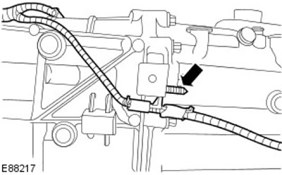
42. Remove the clamp securing the transmission wiring harness on the right side of the transmission.
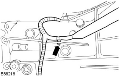
43. Remove the transmission wiring harness clip from the top of the transmission.
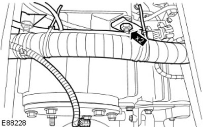
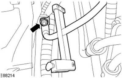
44. Turn away a nut and a bolt of fastening of a basic arm of a hose of the working cylinder of coupling. Install a suitable clamp on the clutch slave cylinder hose.
45.
CAUTION: Plug all openings. Use new caps.
Disconnect the hose from the clutch slave cylinder.
- Remove the clutch slave cylinder tube clamp.
- Remove the O-ring and send it for recycling.
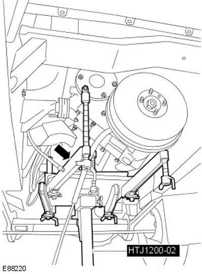
46. Install the special tool HTJ1200-02 on the gearbox and transfer case.
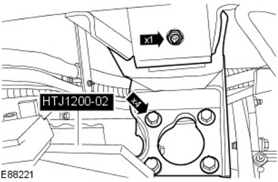
47. Remove the left support and transmission support bracket. Turn away nuts and bolts of fastening of the left support and a basic arm of a transmission.
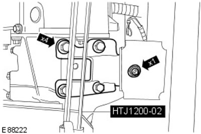
48. Remove the right transfer case support bracket. Turn away nuts and bolts of fastening of the right support and a basic arm of a distributing box.
49. Turn out bolts of forward section of a crankcase.
50. Remove the gearshift housing.
- Move the transmission to provide access to the shift housing.
- Remove from under the car.
- Remove the rubber seal.
51.
CAUTION: Before lowering the HTJ1200-02, move the gearbox 30mm away from the clutch to prevent damage to the gearbox.
Remove the gearbox and transfer case from the vehicle.
52.
NOTE: Do not proceed with further dismantling if the element is removed only for access.
Remove the gearbox from the special tool.
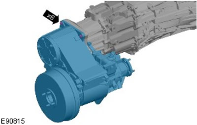
53. Together with an assistant, remove the transfer case.
- Turn out 4 bolts.
- Loosen 2 nuts.
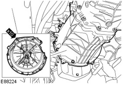
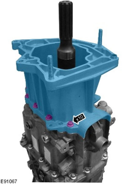
54. Remove the transmission console housing. Remove 10 bolts.
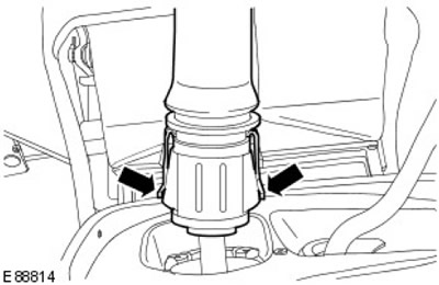
55. Remove the transmission extension shaft cover.
- Remove clamp.
- Remove the cover.
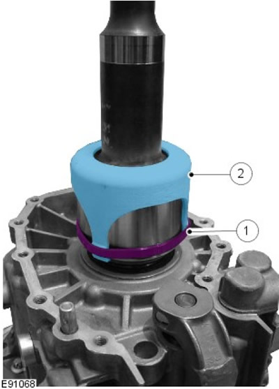
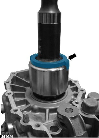
56. Remove the seal.
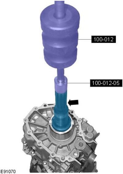
57. Using the special tools, remove the transmission extension shaft.
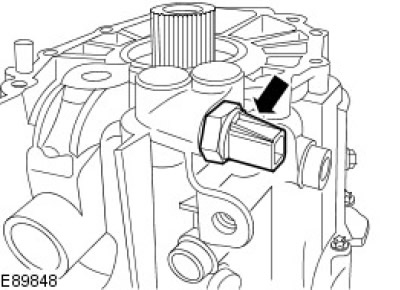
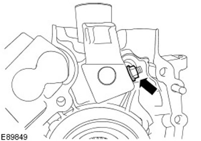
58. Remove the reversing light switch.
59. Remove the clutch slave cylinder.
- Remove the connecting tube retainer.
- Remove the connecting tube.
- Turn out 3 bolts.
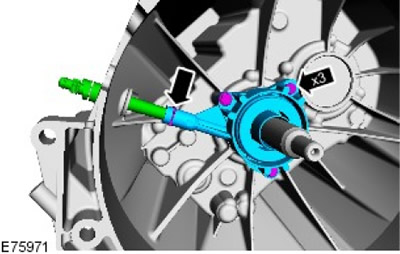
60. Remove a nut of fastening of a fork of the mechanism of a gear change.
61. Using the special tool, remove the shift fork. Unscrew the pin.
Comments on this article