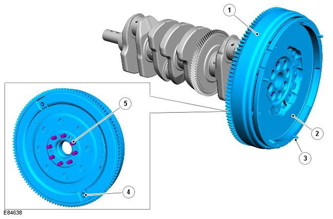
| Pos. | Spare part number | Name |
| 1 | - | Double flywheel |
| 2 | - | Clutch driven disc surface |
| 3 | - | Clutch housing mounting pin (3 pcs.) |
| 4 | - | Installation location of the special tool for adjusting the ignition timing |
| 5 | - | Bolt (8 pcs.) |
A dual flywheel is installed on vehicles with a manual transmission. Vehicles with an automatic transmission are equipped with a torque converter faceplate.
The dual mass flywheel consists of a primary and secondary section which transmit torque to the gearbox via a clutch disc. The secondary section is supported by a roller bearing located in the primary section. The primary section is secured to the flanged rear end of the crankshaft by eight bolts. Torque is transmitted between the primary and secondary sections via a torsion spring vibration damper. The flywheel ensures a constant speed of rotation transmitted to the gearbox and eliminates torsional and transient vibrations generated by the engine.
The outer surface of the flywheel is machined to provide a smooth surface for the clutch disc to engage. Three pins, equally spaced around the outer edge of the secondary section, are used to locate the clutch housing assembly. The flywheel is dynamically balanced to eliminate vibrations generated by the rotating assembly.
A ring gear on the outer perimeter of the primary section provides starter engagement.
There are two holes on the engine side of the dual flywheel. The larger diameter hole is used to install a special tool for adjusting the ignition timing.
Comments on this article