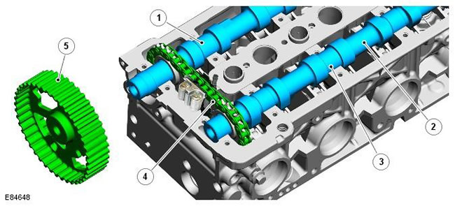
| Pos. | Spare part number | Name |
| 1 | - | Exhaust camshaft |
| 2 | - | Intake camshaft |
| 3 | - | Bearing No.3 (axial clearance control) |
| 4 | - | Single row timing chain |
| 5 | - | Exhaust camshaft pulley |
The intake and exhaust camshafts are made of cast iron. The two camshafts are mounted between the camshaft cover and the cylinder head, with each camshaft located in five machined bearing housings. Bearing liners are not used in the bearing housings; the camshafts rotate directly in aluminum bearings. The axial clearance of the camshafts is controlled by the bearing of camshaft No.3 and is not adjustable. The bearing for ensuring the correct axial clearance is an integral part of each camshaft.
NOTE: During manufacturing, the camshaft end play is set in the range of 0.070 mm to 0.168 mm. During servicing, if the end play is not within specification, it may be necessary to replace the camshaft(s) and/or cylinder head and camshaft cover.
Each camshaft has 8 machined cams arranged in pairs along the length of the camshaft. Camshaft cams are used to actuate the intake and exhaust valves by means of hydraulic clearance compensators and roller valve levers.
A 19-tooth sprocket is provided at the front end of each camshaft. Two sprockets are connected by a 40-link single-row chain of the gas distribution mechanism. Two sprockets of camshafts are marked with adjustment marks, which are combined with two colored links of the chain of the gas distribution mechanism. A slot at the rear end of each camshaft is used to actuate the flange-mounted vacuum pump and the high-pressure fuel pump. The vacuum pump is driven by an intake camshaft; the high pressure fuel pump is driven by the exhaust camshaft.
The exhaust camshaft is driven from the crankshaft pulley by means of a timing belt. The exhaust camshaft pulley has 42 teeth and is secured by means of a key and bolts to the front end of the exhaust camshaft. The intake camshaft is driven by the exhaust camshaft by means of a single-row chain.
The exhaust camshaft pulley has cutouts and a groove in the central hub. The cutouts form a pulse zone for the CMP sensor. The groove is used to install a special tool - a rod for adjusting the ignition timing. This special tool is used in combination with other special tools to adjust the position of the exhaust camshaft when setting the ignition timing.
For more information on adjusting valve timing, refer to the appropriate Service Repair Procedures (SRP) manual.
Adjusting the valve timing
The valve timing values are given in the following table:
| Valve | Position |
| Opening the intake valve | 15 degrees before TDC |
| Closing the intake valve | 12 degrees after BDC |
| Opening the exhaust valve | 23 degrees before BDC |
| Closing the exhaust valve | 17 degrees after TDC |
Transcript:
- Before TDC = before top dead center
- After BDC = after bottom dead center
- Before BDC = before bottom dead center
- After TDC = after top dead center
[The text of the article was taken from the website LRMAN.ru]
Comments on this article