Contents: Removal ⇩ Installation ⇩
Special tool
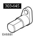 Positioning tool 303-645 Positioning tool 303-645 | 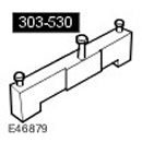 Camshaft Installation/Locking Tool 303-530 Camshaft Installation/Locking Tool 303-530 | 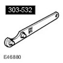 Timing Chain Tensioner Tool 303-532 Timing Chain Tensioner Tool 303-532 |
Removal
1. Disconnect the ground cable from the battery. For more information, refer to Specification.
2. Remove the battery tray. For more information, refer to Battery Mounting Shelf (76.10.30)
3.
CAUTION: Never work on a vehicle supported only by a jack. Always support the vehicle with special stands.
Raise and support the vehicle.
4. Remove the engine front cover. For more information, refer to Engine Front Cover (12.65.01)
5. Remove the crankshaft position sensor (sKR sensor). For more information, refer to Crankshaft Position Sensor (CPS) (18.30.12)
6. Turn the crankshaft until the flat surfaces on the camshafts are parallel to the contact surfaces of the cylinder head.
7.
NOTE: The engine is now in the SAFE position.
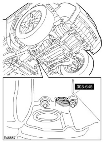
Block the crankshaft.
- Install the special tool in place.
- Screw in the screw.
8. Remove the right camshaft variable valve timing (VCT) unit.
- Remove 3 bolts.
- Remove and discard the O-rings.
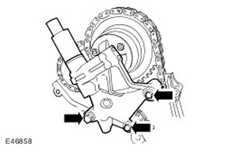
9. Install the special tool on the right-hand cylinder head. Screw in three bolts.
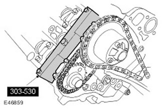
10. Remove the right primary timing chain tensioner. Remove the two bolts.

11. Remove the right primary timing chain tensioner guide. Remove the bolt.
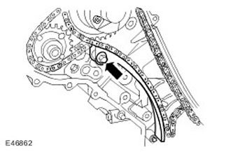
12. Remove the right primary timing chain.
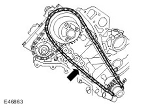
13. Remove the left camshaft variable valve timing (VCT) unit. Remove the two bolts.
- Remove the nut.
- Remove and discard the O-rings.
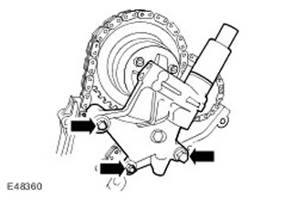
14. Install the special tool on the left-hand cylinder head. Screw in three bolts.
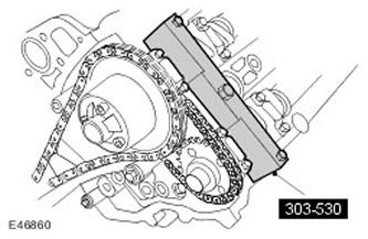
15. Remove the left primary timing chain tensioner. Remove the two bolts.
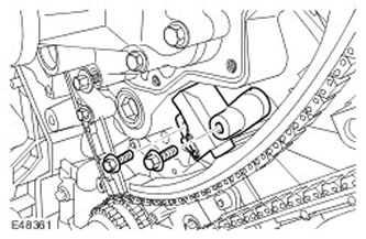
16. Remove the upper and lower guides of the left primary timing chain tensioner.
- Turn out the pin.
- Remove the bolt.
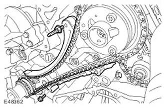
17. Remove the left primary timing chain.
18.
CAUTION: Discard the bolts as they are no longer needed.
Remove the camshaft sprockets. Remove the two bolts.
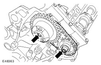
19. Remove the secondary timing chain tensioner and the secondary timing chain. Remove the two bolts.
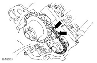
20. Remove the special tool from the left-hand cylinder head. Remove the 3 bolts.
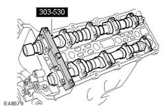
21.
CAUTION: Loosen the camshaft bearing caps evenly and gradually.
NOTE: Remove the camshaft bearing caps. Note: Remember their position, direction and marking. Each cap is marked with its position (number) and direction (arrow).
Remove the camshaft bearing caps. Remove 20 bolts.
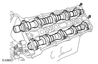
22. Remove the camshafts.
Installation
1. Check and adjust valve lifter clearances.
2. Replace the valve adjusting shims with thinner shims from those available. Apply a thin film of clean engine oil to the new valve adjusting shims.
3. Install the camshafts.
- Clean the contact surfaces of the parts.
- Lubricate the camshaft journals and cams.
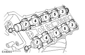
5. Screw the sprocket mounting bolts with a Torx head into the camshafts.
6.
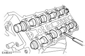
CAUTION: The camshaft lobes must be rotated 180 degrees from the corresponding valve lifters, otherwise the valve clearance will be incorrect.
Measure and record the valve clearances. Turn the sprockets using the Torx head bolts.
7.
NOTE: Loosen the camshaft bearing caps evenly and gradually.
NOTE: Remove the camshaft bearing caps. Note: Remember their position, direction and marking. Each cap is marked with its position (number) and direction (arrow).
Remove the camshafts. Remove 20 bolts.
8. Remove the valve lifters and replace them with the selected lifters.
9. Install the camshafts.
- Lubricate the camshaft journals and cams.
- Clean the contact surfaces of the parts.
11.
CAUTION: The camshaft lobes must be rotated 180 degrees from the corresponding valve lifters, otherwise the valve clearance will be incorrect.
[Original version of the article on the website: lrman.ru]
Check that the valve clearances are adjusted correctly.
- Turn the sprockets using the Torx head bolts.
- Once the inspection is complete, remove the Torx head bolts from the camshafts.
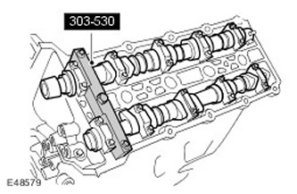
13.
NOTE: The illustration shows the right side, the procedure is similar on the left side.
Press the piston of the secondary timing chain tensioner on the left side. Hold the chain tensioner piston with a 1 mm diameter metal pin.
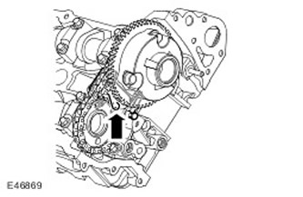
14. Install the left side secondary timing chain tensioner and chain onto the camshaft sprockets.
15. Screw in the bolts securing the left-hand secondary timing chain tensioner. Tighten the bolts. (tightening torque 12 Nm).
16.
NOTE: Lightly tighten the Torx head bolts securing the sprocket to the camshaft, the sprockets MUST move freely.
Install the left side secondary timing chain tensioner and sprockets onto the camshafts. Install the Torx head bolts to secure the sprocket to the camshafts.
17. Tighten the secondary timing chain. Remove the pin.
18. Install the left side primary timing chain. Make sure the slack side of the timing chain is on the tensioner side.
19. Install the left side primary timing chain tensioner guide. Tighten the stud. (tightening torque 12 Nm).
20.
CAUTION: When compressing the tensioner, do not release the ratchet until the tensioner piston is fully retracted into the hole. Failure to do so will result in damage to the ratchet.
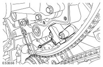
Install the left side primary timing chain tensioner.
- Use a 3mm diameter metal pin to hold the chain tensioner piston.
- Tighten the bolts (tightening torque 12 Nm).
- Remove the pin.
21.
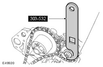
CAUTION: Apply counterclockwise force to the special tool to tighten the primary timing chain on its running side.
CAUTION: The intake camshaft sprocket bolt MUST be tightened before the exhaust camshaft sprocket bolt. Failure to do so will result in engine damage.
Install the special tool on the exhaust camshaft sprocket.
- Tighten the intake camshaft sprocket mounting bolt. (tightening torque 120 Nm).
- Tighten the exhaust camshaft sprocket mounting bolt. (tightening torque 120 Nm).
22. Install the left camshaft variable valve timing (VCT) solenoid housing.
- Install new O-rings.
- Tighten the new bolts. (tightening torque 22 Nm).
- Tighten the nut (tightening torque 10 Nm).
24. Install the right side primary timing chain tensioner guide. Tighten the bolts. (tightening torque 12 Nm).
25.
CAUTION: When compressing the tensioner, do not release the ratchet until the tensioner piston is fully retracted into the hole. Failure to do so will result in damage to the ratchet.
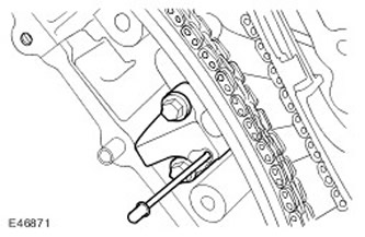
Install the right side primary timing chain tensioner.
- Use a 3mm diameter metal pin to hold the chain tensioner piston.
- Tighten the bolts (tightening torque 12 Nm).
- Remove the pin.
26.
CAUTION: Apply counterclockwise force to the special tool to tighten the primary timing chain on its running side.
CAUTION: The intake camshaft sprocket bolt MUST be tightened before the exhaust camshaft sprocket bolt. Failure to do so will result in engine damage.
CAUTION: Use new bolts.
Install the special tool on the exhaust camshaft sprocket.
- Tighten the intake camshaft sprocket mounting bolt. (tightening torque 120 Nm).
- Tighten the exhaust camshaft sprocket mounting bolt. (tightening torque 120 Nm).
- Install new O-rings.
- Tighten the new bolts. (tightening torque 22 Nm).
29. Remove the special tool from the right-hand cylinder head.
30. Remove the crankshaft locking tool. Remove the screw.
31. Install the Crankshaft Position (CKP) Sensor. For more information, refer to Crankshaft Position (CKP) Sensor (18.30.12)
32.
NOTE: Check valve clearances before installing valve covers.
Install the engine front cover. For more information, refer to Engine Front Cover (12.65.01)
33. Install the battery tray. For more information, refer to Battery Mounting Shelf (76.10.30)
Comments on this article