Contents: Removal ⇩ Installation ⇩
Special tool
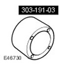 Adapter 303-191-03 Adapter 303-191-03 | 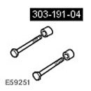 Bolts and bushings 303-191-04 Bolts and bushings 303-191-04 | 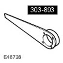 Crankshaft Pulley Locking Tool 303-893(LRT-12-080) Crankshaft Pulley Locking Tool 303-893(LRT-12-080) |
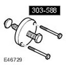 Crankshaft Pulley Puller 303-588 Crankshaft Pulley Puller 303-588 | 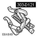 Crankshaft Oil Seal Remover 303-D121 Crankshaft Oil Seal Remover 303-D121 | 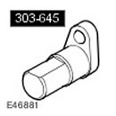 Positioning tool 303-645 Positioning tool 303-645 |
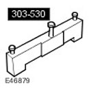 Camshaft Installation/Locking Tool 303-530 Camshaft Installation/Locking Tool 303-530 | 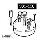 Crankshaft Rear Oil Seal Remover/Installer 303-538 Crankshaft Rear Oil Seal Remover/Installer 303-538 | 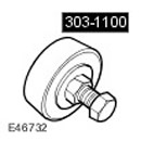 Crankshaft Oil Seal Installation Tool 303-1100 Crankshaft Oil Seal Installation Tool 303-1100 |
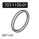 Adapter for crankshaft oil seal installation device 303-1100-01 Adapter for crankshaft oil seal installation device 303-1100-01 |
Removal
1. Disconnect the ground cable from the battery. For more information, refer to Specification.
2.
CAUTION: Never work near or under a vehicle that is raised only by a jack. Always support the vehicle with special stands.
Raise and support the vehicle.
3. Remove the engine. For more information, refer to Engine (12.41.01.99)
4. Install the engine on the engine stand.
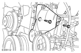
5. Remove the air conditioning compressor support bracket. Remove the two bolts.
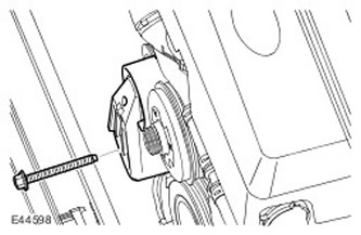
6. Remove the cooling system fan drive belt tensioner. Unscrew the bolt.
7. Remove the cooling system manifold.
- Release the clamps and disconnect the 4 coolant hoses.
- Remove four bolts.
- Disconnect the engine coolant temperature (ECT) sensor electrical connector.
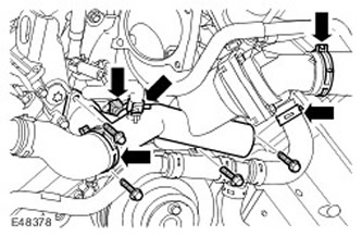
8. Remove the coolant pump pulley and accessory drive belt idler pulleys. Remove the bolts.
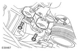
9. Remove the exhaust manifold heat shield. Remove the two bolts.
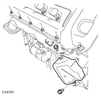
10. Disconnect the positive battery cable.
- Remove the positive battery cable cover.
- Unscrew the nut.
- Disconnect the electrical connector.
- Remove 3 bolts.
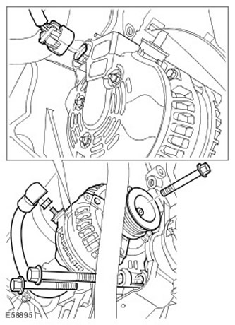
12. Remove the generator support bracket. Remove the four bolts.
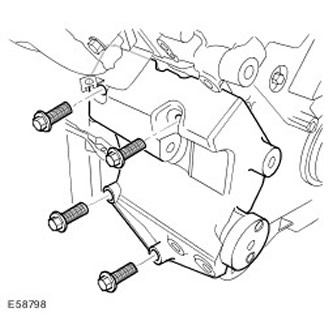
13. Disconnect the electrical connector of the engine oil temperature sensor.
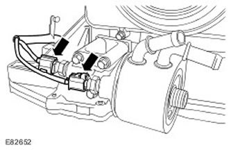
14. Disconnect the electrical connector of the engine oil pressure (EOP) sensor.
15.
NOTE: Some oil will inevitably spill during this operation.
NOTE: Clean the general area of the components before disassembling.
Remove the oil filter.
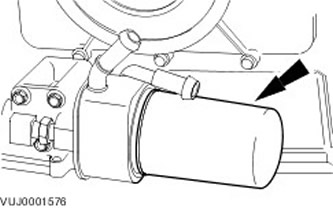
16. Remove the engine oil filter.
- Remove 3 bolts.
- Remove and discard the sealing ring.
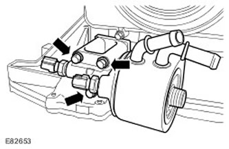
17.
CAUTION: Under no circumstances should the crankshaft dowel pin, 303-645, be used to lock the crankshaft when performing the following procedure.
Using special tools, lock the crankshaft pulley.
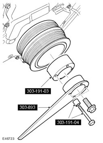
18.
NOTE: The crankshaft pulley mounting bolt is very tight.
Using special tools, remove the crankshaft pulley mounting bolt.
- Discard the bolt.
- Disconnect the special tools.
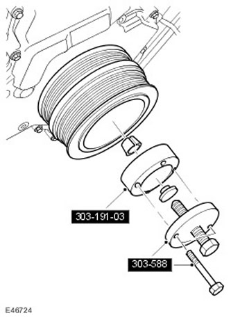
NOTE: The crankshaft pulley is very difficult to remove.
Using special tools, remove the crankshaft pulley.
- Select the retaining ring.
- Disconnect the special tools.
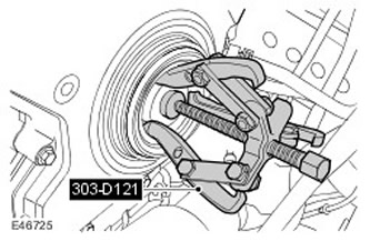
20. Using the special tool, remove the front crankshaft seal and discard it.
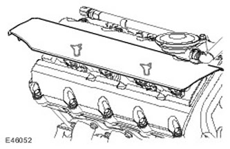
21. Remove the right direct ignition coil cover. Release the two clamps.
22. Disconnect the right electrical connector of the direct ignition coil.
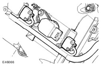
23. Remove the right direct ignition coil.
- Remove the bolt.
- Remove and discard the sealing ring.
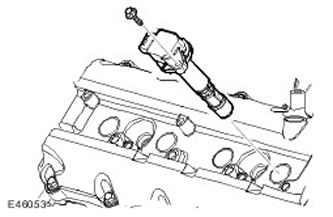
24. Remove the remaining direct ignition coils.
The article is based on data from the website www.LRman.ru
25. Disconnect the positive crankcase ventilation (PCV) line.
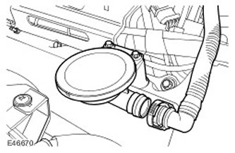
26. Disconnect the left variable valve timing (VCT) solenoid electrical connector.
27. Disconnect the breather from the cylinder head cover.
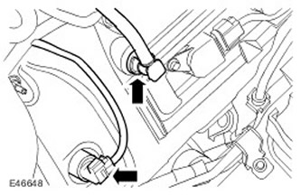
28. Release the engine wiring harness from the support bracket.
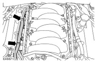
29. Disconnect the right variable valve timing (VCT) solenoid electrical connector.
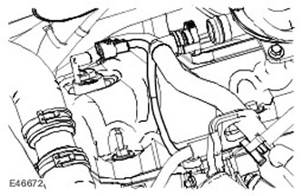
30.
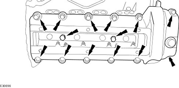
NOTE: Before removing bolts, record their locations.
Remove the right cylinder head cover.
- Remove 14 cylinder head cover mounting bolts.
- Remove the engine cover retainer.
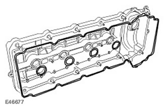
31. Remove and discard the right cylinder head cover gaskets. Remove and discard the seals.
32. Remove the left direct ignition coil cover. Release the two clamps.
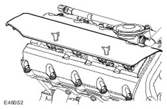
33. Disconnect the left electrical connector of the direct ignition coil.
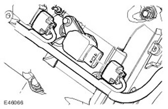
34. Remove the left direct ignition coil.
- Remove the bolt.
- Remove and discard the sealing ring.
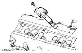
35. Remove the remaining left direct ignition coils.
36. Remove the dipstick and oil level indicator tube.
- Remove the oil level dipstick.
- Unscrew the nut.
- Pick up the phone.
- Remove and discard the sealing ring.
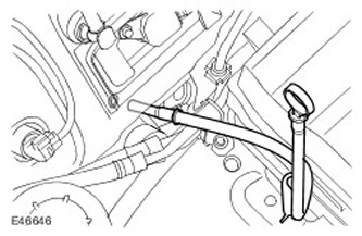
37. Release the engine wiring harness from the support bracket.
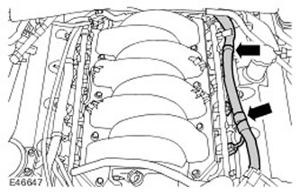
38.
NOTE: Before removing bolts, record their locations.
Remove the left cylinder head cover. Unscrew the 14 cylinder head cover mounting bolts.
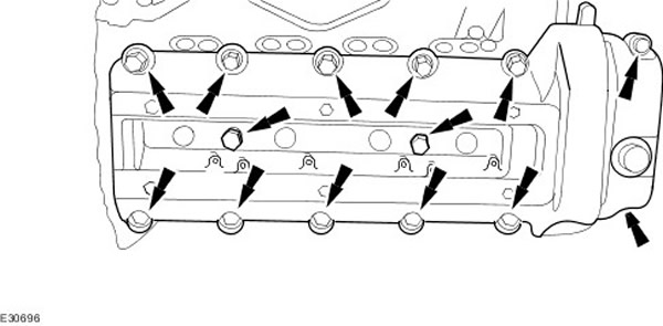
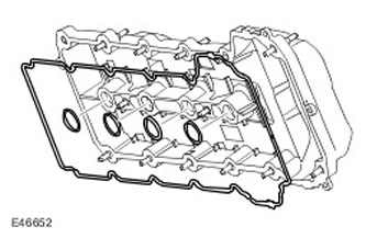
39. Remove and discard the left cylinder head cover gaskets. Remove and discard the seals.
40. Release the engine wiring harness.
- Release the two clamps.
- Remove the bolt.
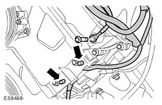
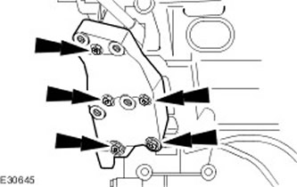
41. Remove the power steering pump support bracket. Remove the five bolts.
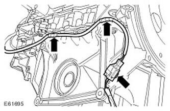
42. Release the wiring harness from its mounting on the left side of the engine. Release the three clamps.
43. Release the wiring harness from its mounting on the right side of the engine. Release the three clamps.
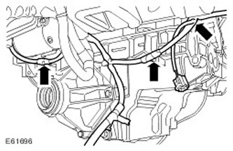
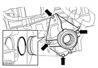
44. Remove the intermediate axle support housing.
- Remove four bolts.
- Remove and discard the sealing ring.
45. Disconnect the crankshaft position sensor (CKP) electrical connector.
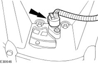
46. Remove the CKP sensor. Unscrew the bolt.
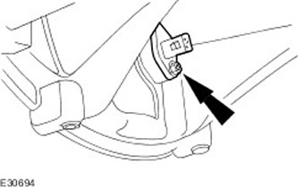
47.
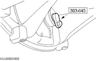
NOTE: Install the special tool into the crankshaft sensor hole.
Block the crankshaft.
- Install the special tool.
- Screw in the screw.
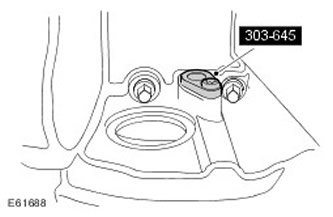
48. Remove the front engine cover.
- Remove 24 bolts.
- Remove and discard the gasket.
- Remove and discard the 3 O-rings.
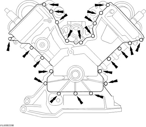
49. Remove the right VCT housing.
- Remove 3 bolts.
- Remove the O-rings and discard them.
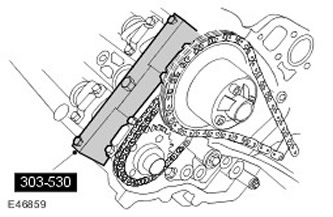
50. Install the special tool on the right cylinder head. Screw in 3 bolts.
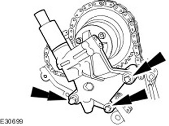
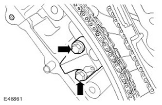
51. Remove the right primary timing chain tensioner. Remove 2 bolts.
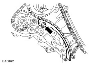
52. Remove the primary timing chain tensioner guide for the right row. Unscrew the bolt.
53. Remove the primary timing chain of the right bank.
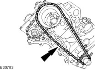
54. Remove the left VCT housing.
- Remove 3 bolts.
- Remove and discard the O-rings.
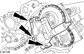
55. Install the special tool on the left cylinder head. Screw in 3 bolts.
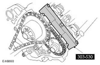
56. Remove the left-hand primary timing chain tensioner. Remove the two bolts.
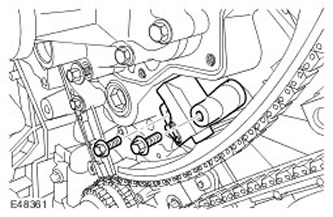
57. Remove the upper and lower guide of the left primary timing chain tensioner. Unscrew the two bolts.
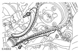
58. Remove the primary timing chain of the left row.
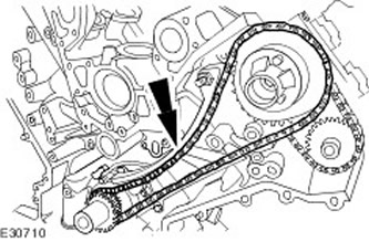
59.
NOTE: Mark the position of the crankshaft sprocket.
Remove the crankshaft sprocket. Remove the crankshaft sprocket cotter pin.
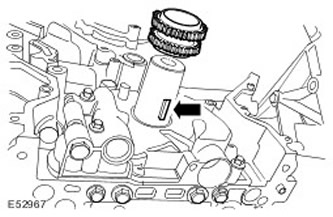
60. Remove the special tool.
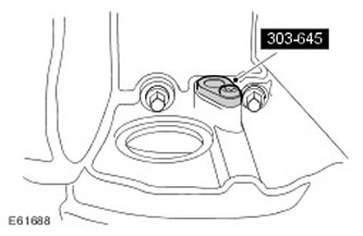
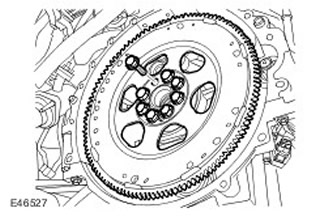
61. Remove the torque converter flexible plate. Unscrew and discard the 8 bolts.
62.
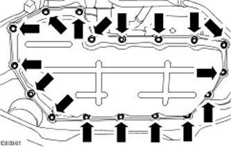
CAUTION: Before removing the bolts, mark their position.
Remove the oil pan.
- Remove 17 bolts.
- Remove and discard the gasket.
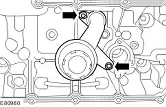
63. Remove the oil inlet pipe with the mesh filter.
- Remove two bolts.
- Remove and discard the sealing ring.
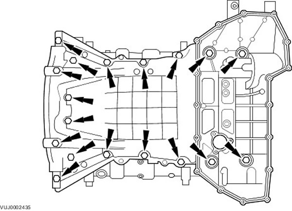
64. Remove the oil pan extension. Remove 18 bolts.
65. Remove the oil pump assembly.
- Remove four bolts.
- Remove and discard the gasket.
- Clean the mating surfaces of the elements.
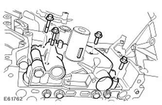
66. Remove the oil deflector plate. Unscrew 6 bolts.
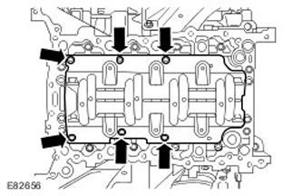
67.
CAUTION: To avoid damage to the crankshaft and piston components, the engine must be upside down on the engine stand. Failure to do so may result in engine damage.
NOTE: If the crankshaft main bearing housing bolts have been spotted, they must be discarded and new bolts installed.
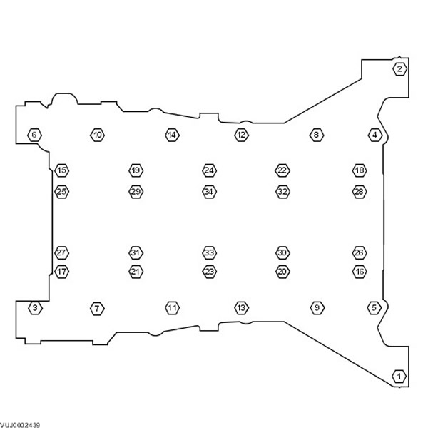
Remove the crankshaft main bearing housing. Unscrew the crankshaft main bearing housing mounting bolts in the specified sequence.
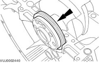
68. Remove and discard the rear crankshaft oil seal.
Installation
1.
CAUTION: Use only a plastic scraper to remove sealant.
CAUTION: If new crankshaft main bearing housing bolts are installed, the bolts must be prestressed by installing the crankshaft main bearing housing without applying sealant and tightening the new bolts to the specified torque. After prestressing the bolts, remove the crankshaft main bearing housing. Failure to do so may result in vehicle damage.
Thoroughly clean all mating surfaces and reusable components and inspect them for damage.
2.
NOTE: Install the crankshaft main bearing housing and tighten the bolts to the specified torque within twenty minutes after applying the sealant.
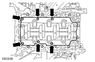
Apply a 2mm bead to the cylinder block at the location shown. Use WSS-M4G323-A4-RTV sealant.
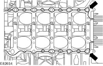
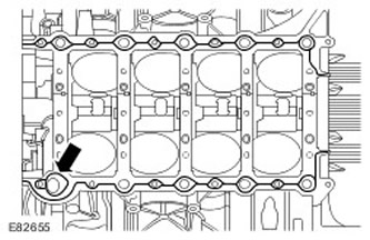
3.
NOTE: Install the crankshaft main bearing housing and tighten the bolts to the specified torque within twenty minutes after applying the sealant.
Apply a 1mm bead to the cylinder block at the location shown. Use WSS-M4G323-A4-RTV sealant.
4.
CAUTION: Before tightening the bolts, make sure all studs are securely fastened in the crankshaft main bearing housing.
NOTE: Do not lubricate the crankshaft main bearing housing bolts.
NOTE: Do not turn the crankshaft until all mounting bolts have been tightened to the specified torque.
NOTE: The mounting bolts must be tightened within twenty minutes after applying the sealant.
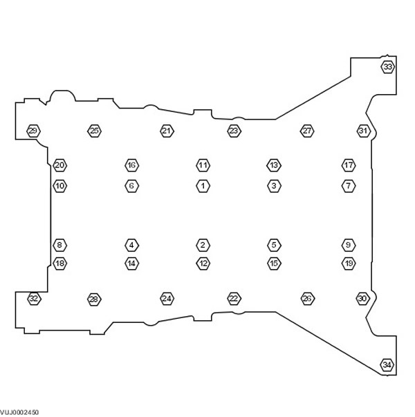
NOTE: Tighten the bolts in the sequence shown.
Install the crankshaft main bearing housing into the cylinder block.
- 1) Stage 1: Bolts 21-32, tightening torque 15 Nm.
- 2) Stage 2: Bolts 33-34, tightening torque 15 Nm.
- 3) Stage 3: Bolts 1-10, tightening torque 25 Nm.
- 4) Stage 4: Bolts 11-20, tightening torque 15 Nm.
- 5) Stage 5: Bolts 1-10, tighten to 35 Nm, then another 135 degrees.
- 6) Stage 6: Bolts 11-20, tightening torque 20 Nm, then another 150 degrees.
- 7) Stage 7: Bolts 21-32, tightening torque 20 Nm, and then another 90 degrees.
- 8) Stage 8: Bolts 33-34, tightening torque 20 Nm, and then another 150 degrees.
- 9) Step 9: Punch the bolt heads to indicate that they have been reused.
5. Remove the special tool.
6. Remove the special tool from the cylinder head.
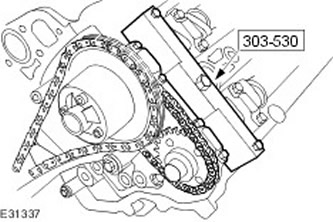
7. Remove the special tool from the right cylinder head.
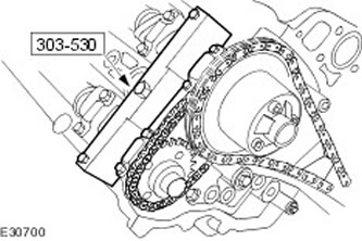
8.
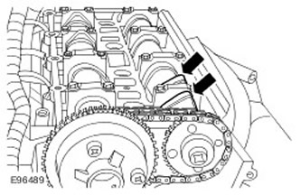
CAUTION: Make sure that the intake camshaft lobes for cylinder #1 are positioned vertically to the cylinder head surface.
Set the right camshafts to neutral position.
9.
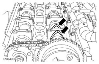
CAUTION: Make sure that the exhaust camshaft lobes for cylinder #2 are positioned vertically to the cylinder head surface.
Set the left camshafts to neutral position.
10.
CAUTION: Make sure the crankshaft is not seized.
CAUTION: The spark plugs must be removed to allow the engine to turn over freely.
Carefully rotate the crankshaft two full revolutions to check for proper operation.
11. Install the oil deflector plate. Tighten the 6 bolts. (tightening torque 6 Nm).
12.
NOTE: Carefully remove the transport sleeve, leaving the oil seal in place.
NOTE: Make sure the transport sleeve is positioned correctly and install the new oil seal onto the crankshaft. Do not apply grease to the oil seal, transport sleeve or crankshaft.
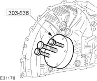
Using the special tool, install the rear crankshaft oil seal. Install the special tool on the crankshaft.
13.
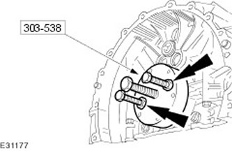
CAUTION: Adjust the nut tightening to properly seat the rear crankshaft oil seal.
Using the special tool, install the rear crankshaft oil seal.
14.
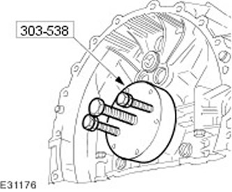
CAUTION: Make sure the crankshaft rear oil seal is installed correctly.
Remove the special tool.
15.
NOTE: Do not allow the flexible plate to rotate.
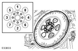
Install the torque converter flexible plate.
- Clean the contact surfaces of the parts.
- Tighten the bolts evenly, working in the sequence shown in two stages.
- Tighten the bolts (tightening torque 15 Nm).
- Tighten the bolts (tightening torque 110 Nm).
16.
CAUTION: The spark plugs must be removed to allow the engine to turn over freely.
CAUTION: Do not turn the crankshaft counterclockwise.
CAUTION: Turn the crankshaft clockwise to the top dead center (TDC) position for cylinder No.1
Install the special tool.
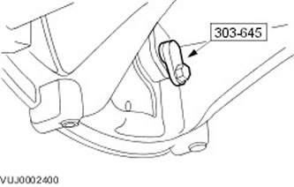
17. Install the special tool on the left cylinder head.
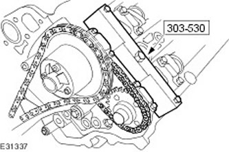
18. Install the special tool on the right cylinder head.
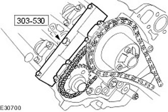
19.
NOTE: Install a new gasket.
Install the oil pump assembly.
- Clean the mating surfaces of the elements.
- Install the gasket.
- Tighten the bolts (tightening torque 10 Nm).
NOTE: Install a new O-ring.
Install the oil inlet pipe with a mesh filter.
- Install the sealing ring.
- Tighten the M6 bolt (tightening torque 10 Nm).
- Apply sealant to the M5 bolts.
- Tighten the M5 bolts (tightening torque 6 Nm).
- Clean the mating surfaces of the elements.
- Install the crankshaft sprocket cotter pin.
23. Install the left bank primary timing chain tensioner guides. Tighten the bolts. (tightening torque 12 Nm).
24.
CAUTION: When compressing the tensioner, do not release the ratchet until the tensioner piston is fully retracted into the hole. Failure to do so will result in damage to the ratchet.
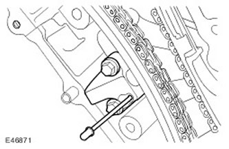
Install the left row primary timing chain tensioner.
- Using a 3mm diameter rod, secure the chain tensioner piston.
- Tighten the bolts (tightening torque 12 Nm).
- Remove the metal rod.
25.
CAUTION: Use new bolts.
NOTE: Install new O-rings.
Install the left variable valve timing (VCT) solenoid valve housing.
- Install the sealing rings.
- Tighten the bolts (tightening torque 22 Nm).
- Tighten the nut (tightening torque 10 Nm).
27. Install the right bank primary timing chain tensioner guide. Tighten the bolts. (tightening torque 12 Nm).
28.
CAUTION: When compressing the tensioner, do not release the ratchet until the tensioner piston is fully retracted into the hole. Failure to do so will result in damage to the ratchet.
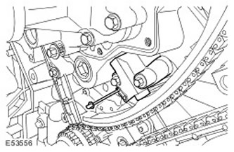
Install the right row primary timing chain tensioner.
- Using a 3mm diameter rod, secure the chain tensioner piston.
- Tighten the bolts (tightening torque 12 Nm).
- Remove the metal rod.
29.
CAUTION: Use new bolts.
NOTE: Install new O-rings.
Install the right variable valve timing (VCT) solenoid valve housing.
- Install the sealing rings.
- Tighten the bolts (tightening torque 22 Nm).
- Tighten the nut (tightening torque 10 Nm).
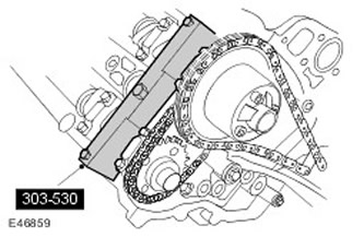
31. Remove the special tool from the left cylinder head.
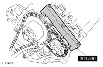
32. Remove the oil pan extension.
- Clean the mating surfaces of the elements.
- Apply a 3mm bead of sealant to the area shown.
- Screw in the bolts, but do not tighten them completely yet.
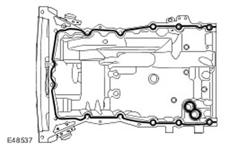
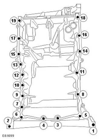
33. Tighten the oil pan bolts in the sequence shown. (tightening torque 20 Nm).
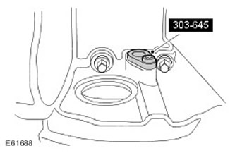
34. Remove the special tool. Unscrew the bolt.
35. Install the CKP sensor. Tighten the bolt. (tightening torque 8 Nm).
36. Secure the wiring harness to the bracket on the left side of the engine. Secure with clamps.
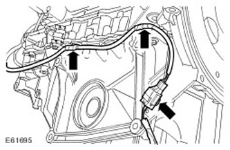
37. Secure the wiring harness to the bracket on the right side of the engine. Secure the clamps.
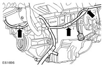
38. Install the power steering pump support bracket. Tighten the bolts. (tightening torque 25 Nm).
39.
NOTE: Install a new gasket.
NOTE: Install a new O-ring.
Install the front engine cover.
- Clean the mating surfaces of the elements.
- Apply the sealant in a 3mm diameter, 12mm long bead to the 8 indicated locations.
- Install the gasket.
- Install the sealing ring.
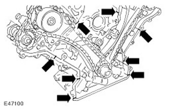
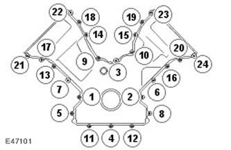
40. Tighten the bolts evenly and gradually in the sequence shown. (tightening torque 12 Nm).
41. Secure the engine wiring harness.
- Secure with clamps.
- Tighten the bolt (tightening torque 10 Nm).
NOTE: Install new seals.
Install new seals into the left cylinder head cover holes.
43.
NOTE: Install a new gasket.
NOTE: Apply two beads of silicone gasket sealant as shown in the illustration. The beads of sealant should be 3 mm in diameter and 12 mm long. Install the cylinder head cover immediately after applying the sealant. The cylinder head cover must be installed directly onto the head without smearing the sealant on the gasket.
Install the left cylinder head cover.
- Clean the mating surfaces of the elements.
- Install the cylinder head cover gasket.
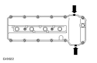
44. Screw in the bolts of the left cylinder head cover.
- Screw in the left cylinder head cover bolts in accordance with their previous location.
- Tighten the bolts in the sequence shown. (tightening torque 12 Nm).
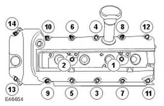
45. Connect the electrical connector of the left-hand variable valve timing (VCT).
46. Insert the engine wiring harness into the support bracket.
47.
NOTE: Install a new O-ring.
With assistance, install the oil level indicator and tube.
- Clean the mating surfaces of the elements.
- Install the sealing ring.
- Lubricate the O-ring with clean engine oil.
- Tighten the nut (tightening torque 6 Nm).
NOTE: Install new O-rings.
Install 4 left direct ignition coils.
- Install the sealing rings.
- Install 4 direct ignition coils.
- Tighten the bolts (tightening torque 6 Nm).
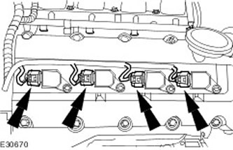
50. Install the left direct ignition coil cover.
51.
NOTE: Install new seals.
Install new seals into the right cylinder head cover holes.
52.
NOTE: Install a new gasket.
NOTE: Apply two beads of silicone gasket sealant as shown in the illustration. The beads of sealant should be 3 mm in diameter and 12 mm long. Install the cylinder head cover immediately after applying the sealant. The cylinder head cover must be installed directly onto the head without smearing the sealant on the gasket.
Install the right cylinder head cover.
- Clean the mating surfaces of the elements.
- Install the gasket.
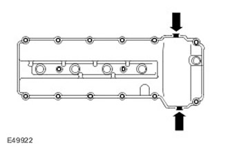
53. Screw in the bolts of the right cylinder head cover.
- Reinstall the right cylinder head cover bolts in their original locations.
- Tighten the bolts in the sequence shown. (tightening torque 12 Nm).
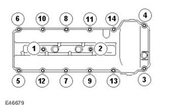
54.
NOTE: Install new O-rings.
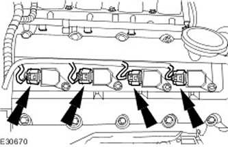
Install 4 right direct ignition coils.
- Install the sealing rings.
- Install 4 direct ignition coils.
- Tighten the bolts (tightening torque 6 Nm).
56. Connect the electrical connector of the right-hand variable valve timing (VCT).
57. Insert the engine wiring harness into the support bracket.
58. Connect the PCV line to the right cylinder head cover.
59. Clean the contact surfaces of the crankshaft pulley.
60. Using the special tool, install the front crankshaft oil seal.
- Lubricate the seal with clean engine oil.
- Use the scrap crankshaft bolt with the special tool.
- Disconnect the special tools.
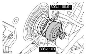
61. Install the crankshaft pulley. Lubricate the seal with clean engine oil.
62. Install the crankshaft pulley retaining ring.
63.
CAUTION: Before installing a new crankshaft pulley bolt, it is necessary to clean the threads in the pulley.
Install the crankshaft pulley bolt, but do not tighten it.
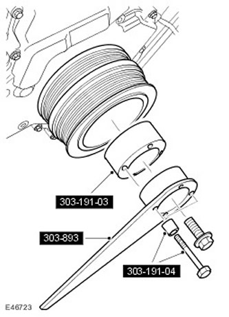
64.
CAUTION: Under no circumstances should the crankshaft dowel pin, 303-645, be used to lock the crankshaft when performing the following procedure.
Using special tools, tighten the crankshaft pulley mounting bolt.
- Tighten the crankshaft pulley mounting bolt. (tightening torque 380 Nm).
- Remove special tools.
65. Install the oil filter housing.
- Clean the mating surfaces of the elements.
- Install a new O-ring.
- Tighten the bolts (tightening torque 20 Nm).
67. Connect the electrical connector of the engine oil pressure (EOP) sensor.
68. Connect the electrical connector of the engine oil temperature sensor.
69. Install the generator support bracket. Tighten the 4 bolts. (tightening torque 45 Nm).
70. Install the generator.
- Tighten the 3 bolts (tightening torque 48 Nm).
- Connect the electrical connector.
- Tighten the nut (tightening torque 10 Nm).
- Install the positive battery cable cover.
73. Install the accessory drive belt idler pulleys. Tighten the bolts. (tightening torque 25 Nm).
74. Install the coolant pump pulley. Tighten the bolts. (tightening torque 10 Nm).
75.
NOTE: Install new O-rings.
Install the cooling system manifold.
- Clean the parts.
- Install the sealing rings.
- Connect the 4 coolant hoses and install the clamps.
- Install the wiring harness bracket.
- Tighten the Torx head screws (tightening torque 10 Nm).
77. Install the cooling fan drive belt tensioner. Tighten the bolt. (tightening torque 40 Nm).
78. Install the air conditioning compressor support bracket. Tighten the bolts. (tightening torque 25 Nm).
79. Remove the engine from the stand.
80. Install the engine. For more information, refer to Engine (12.41.01.99)
81. Connect the ground cable to the battery. For more information, refer to Specification.
Comments on this article