


Contents: Removal ⇩ Installation ⇩
Special tool
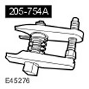 Ball Joint Puller 205-754 (LRT-54-027) Ball Joint Puller 205-754 (LRT-54-027) |
Removal
1. Disconnect the ground cable from the battery. For more information, refer to Specification.
2.
CAUTION: Never work on or under a vehicle that is supported solely by a jack. Always support the vehicle securely.
Raise and support the vehicle.
3. Remove the right front wheel.
4. Remove the engine protection shield. For more information, refer to Engine Protection (76.10.50)
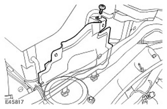
5. Remove the right upper heat shield of the engine compartment. Unscrew the screw.
6.
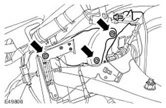
NOTE: The heat shield consists of three parts.
To gain access, remove the upper control arm and brake line heat shields.
- Unscrew 3 nuts.
- Remove 3 bolts.
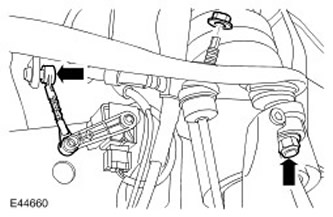
7. Disconnect the height sensor lever.
8.
CAUTION: To prevent the ball joint from turning, use the supplied Allen key.
Loosen the stabilizer bar mounting nut.
9.
CAUTION: To prevent the steering knuckle from falling forward and separating the inner axle joint, support the steering knuckle.
Loosen the upper arm mounting nut.
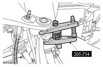
10. Using the special tool, disconnect the upper arm ball joint. Unscrew the nut and discard it.
11. Disconnect the brake hose from the upper arm.
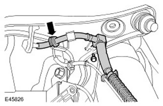
12. To gain access, move the upper control arm to the side and tie it down.
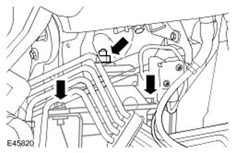
13. Support the engine.
14. Raise the engine. Unscrew the nut.
15. Remove the front engine mount. Unscrew and discard the 2 bolts.
Installation
1. Clean the contact surfaces of the parts.
2. Install the front engine mount. Tighten the bolts to 45 Nm, then tighten them an additional 60 degrees.
3. Lower the engine onto the support. Tighten the nut. (tightening torque 90 Nm).
4. Remove the support from under the engine.
5. Attach the brake hose to the upper arm. Tighten the bolt. (tightening torque 23 Nm).
6. Connect the upper arm to the steering knuckle.
- Remove the clamp securing the upper control arm.
- Screw on the new nut and tighten it. (tightening torque 70 Nm).
8. Attach the height sensor lever.
9.
NOTE: The heat shield consists of three parts.
Install the upper control arm and brake line heat shields.
- Screw in the bolts.
- Tighten the nuts.
11. Install the engine protection screen. For more information, refer to Engine Protection (76.10.50)
12. Install the front wheel. Tighten the wheel nuts. (tightening torque 140 Nm).
Comments on this article