Examination
1. Disconnect a wire of weight from the storage battery.
2. Remove the cooling fan. Cooling Fan (26.25.19)
3. Remove a cover of the left head of cylinders. Left valve cover (12.29.43)
4. Remove a cover of the right head of cylinders. Right valve cover (12.29.44)
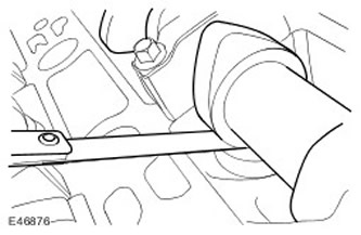
5.
CAUTION: The camshaft lobes must be rotated 180 degrees from their respective valve lifters or the valve clearance will be incorrect.
Turn the engine crankshaft clockwise so that the camshaft lobe moves away from the valve lifter
6. Using a feeler gauge, measure the clearance between the camshaft and the valve lifter.
7. Repeat the above procedure for the remaining 31 valve lifters.
8. Adjust clearance if necessary.
9. See technical specifications for cylinder head dimensions. Specification.
10. Establish a cover of the right head of cylinders. Right valve cover (12.29.44)
11. Establish a cover of the left head of cylinders. Left valve cover (12.29.43)
12. Install the cooling fan. Cooling Fan (26.25.19)
13. Connect a wire of weight to the storage battery. Specification.
Adjustment
NOTE: Valve clearance adjustment is part of the camshaft removal and installation procedure.
1. Remove camshafts. Right camshafts (12.13.20)
2. Install the camshafts. Right camshafts (12.13.20)
Comments on this article