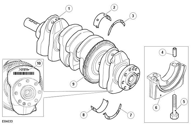
| Pos. | Spare part number | Name |
| 1 | - | Crankshaft |
| 2 | - | Upper main bearing shell (4 pcs.) |
| 3 | - | Upper thrust washer (2 pcs.) |
| 4 | - | Main bearing cap dowel pin No.1 (2 pcs.) |
| 5 | - | Main bearing cap bolts (10 pcs.) |
| 6 | - | Main bearing cap (5 pcs.) |
| 7 | - | Lower thrust washer (2 pcs.) |
| 8 | - | Lower main bearing shell (4 pcs.) |
| 9 | - | Balance shaft drive gear |
| 10 | - | Classification marking of main bearings |
The crankshaft is made of steel and contains five main bearing journals and four connecting rod bearing journals. The main bearing journals are located in the main bearing housings of the cylinder block and are fixed by means of five main bearing caps. Each main bearing cap is stamped with the corresponding cylinder number for identification. The main bearing cap marked '1F' should be located on the side of the engine facing the gearbox (No. 1, on the edge).
The axial movement of the crankshaft is limited by four semicircular thrust washers, which are located on both sides of the main bearing No.2. The thrust washers are provided with lubrication grooves, which must face the main bearing. The axial clearance of the crankshaft should be from 0.07 mm to 0.32 mm.
Each main bearing housing and cap has an upper and lower shell made of aluminum/tin. The upper shells have a hole and annular groove to carry pressurized oil from the main bearing, through the crankshaft bores, to the connecting rod bearings.
The main bearing caps and the upper and lower bearing shells have lugs. The lugs ensure correct alignment of the bearing and cap and prevent radial movement of the bearing.
To maintain the required crankshaft main bearing clearance, main bearing shells of different thicknesses are provided. The upper main bearing shell is offered in only one size option, the lower main bearing shells have five size options. The upper and lower main bearing shells are color-coded for identification purposes. To select the correct size of bearing shells, classification markings on the crankshaft face and on the cylinder block face, as well as a table of bearing sizes are used.
For additional information on installing main bearing shells, refer to the appropriate Service Repair Procedures (SRP) manual.
The drive pinion is hot-pressed onto crankshaft journal No.3, which is located between main bearing journal No.2 and connecting rod bearing journal No.2. This helical drive pinion drives the balancer gears. At the front end of the crankshaft, behind the front crankshaft seal plate, is an 18-tooth sprocket. The sprocket drives the oil pump assembly via a single-row chain and is secured to the crankshaft with a segment key.
A toothed pulley mounted on the front end of the crankshaft drives the timing belt. The pulley has 21 teeth and is secured to the crankshaft by means of a woodruff key.
Comments on this article