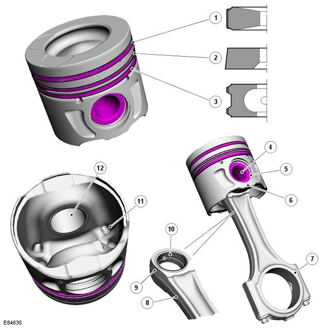
| Pos. | spare part no | Name |
| 1 | - | Top compression ring |
| 2 | - | Lower compression ring |
| 3 | - | Oil scraper ring |
| 4 | - | piston pin |
| 5 | - | Piston pin circlip (2 pcs.) |
| 6 | - | Piston with connecting rod |
| 7 | - | The bottom head of the connecting rod |
| 8 | - | Connecting rod body |
| 9 | - | Upper connecting rod head |
| 10 | - | Connecting rod bearing |
| 11 | - | Piston head cooling channel |
| 12 | - | Piston sleeve (2 pcs. on the piston) |
The connecting rods are made from forged steel and have an 'I' body design for high strength and durability. The top end of the connecting rod tapers on each side to form a cone. The conical shape improves the distribution of forces between the piston and connecting rod during the combustion stroke. A bronze bushing is installed on the top head, it has an internal groove that allows lubricating oil to flow around the bushing.
The bottom end of the connecting rod is cut and machined at the joint to form a bearing housing and a bearing cap that is attached with two bolts. The cylinder number is stamped on the mating surfaces to identify paired connecting rods and bearing caps. In each half of the lower head of the connecting rod, a liner is installed. Connecting rod bearing housings and shells have ridges that ensure proper alignment of the bearing in the housing and prevent radial movement of the bearing shells. When installing, the tabs must face the left side of the engine (to the oil filter side).
To maintain the required clearance in the connecting rod bearing of the crankshaft, bearing shells of different thicknesses are provided. The lower bearing shell is only available in one size, the upper bearing shells are available in three sizes.
For more information on installing connecting rod bearings, see the appropriate Service and Repair Procedures Manual (SRP).
The pistons are made of aluminum alloy and equipped with two compression rings and an oil scraper ring with a coil spring. A steel insert is inserted into the groove of the upper piston ring for reinforcement. The piston crown has a toroidal shape with a pronounced cup-shaped section in the center of the piston head. The piston crown also has recesses to provide space for four valve heads. The design of the combustion chamber contributes to the high levels of swirl and turbulence required for complete combustion of the air-fuel mixture, as well as to reduce engine emissions.
The three piston rings must be installed so that the locks are spaced 120°apart (with a tolerance of 15°- 20°) one from the other around the perimeter of the piston. Top two compression rings are embossed with markings for easy installation "Top". The trapezoidal oil scraper ring lock must be located on the opposite side of the expansion coil spring joint.
The full skirt piston is coated with a graphite-based compound to reduce friction in the cylinder. The graphite-based composition plays a particularly important role during the engine's run-in period and during start-up. The piston also has two oil cooling channels located on the back of the piston head.
Two bushed holes are provided on opposite sides of the piston skirt for the installation of a fully floating piston pin. The piston pin passes through the bushed piston bores and the top end of the connecting rod and is secured at both ends with a circlip. The oil for the piston, piston pin, and connecting rod head comes from an oil nozzle, which is located under each cylinder.
When installing pistons, the embossed arrow and 'DIST' designation on each piston crown must face the front of the engine (to accessory drive end).
For more information about installing pistons and piston rings, see the appropriate Service and Repair Procedures Manual (SRP).
Comments on this article