Removal
1. Remove the oil pump.
ENGINE TD6, REPAIR WORK, Oil pump.
Disassembly
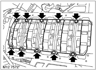
1. Unscrew the 10 bolts securing the lower plate of the cylinder block and remove the plate.
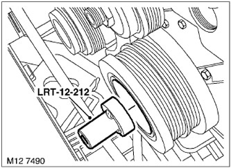
2. Using the LRT-12-212 tool installed on the crankshaft pulley, rotate the shaft to gain access to the connecting rod bolts.
3. Mark the connecting rods and connecting rod caps according to cylinder numbers.
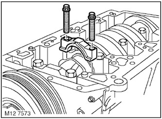
4. Loosen and remove the connecting rod bolts, save them for this step.
CAUTION: The connecting rod caps are installed on pins. Avoid side impacts on the caps.
5. Remove the connecting rod caps, remove and discard the connecting rod bearings.
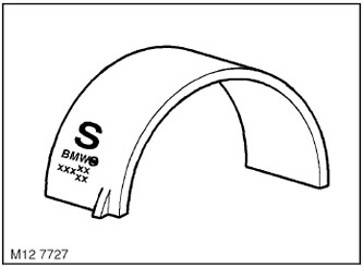
6. Turn the crankshaft to be able to move the connecting rod away from the crankshaft journal.
CAUTION: The upper connecting rod bearings have a running-in coating and are marked with the letter "S" or a series of "xxx" symbols on their back side.
7. Remove and discard the upper connecting rod bearings, making sure they have an "S" mark on the back.
See the source on the website: lrman.ru
8. Do the same with the remaining connecting rod bearings. Lay out the connecting rod caps in the order in which they were on the engine.
Examination
1. Wipe the connecting rod journals, new bearings, and the upper and lower bearing beds.
2. Measure the diameter of each crankpin in four directions at 90°. Record the measurement results.
3. Wipe the connecting rod bolts and lubricate them with engine oil.
4. Turn the crankshaft so that the connecting rod journals of the first and sixth cylinders are at TDC.
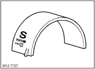
5. Install new bearing shells, marked BLUE with the letter "S", into the connecting rods of the first and sixth cylinders.
6. Install new bearing shells, marked RED, into the connecting rod caps of the first and sixth cylinders.
7. Place both connecting rods onto the crankpins.
8. Place strips of deformable gauge on the connecting rod journals of the first and sixth cylinders, in the axial direction.
9. After aligning the marks, install the connecting rod caps in their places.
10. Screw in the old connecting rod bolts and tighten them:
- Stage 1 - 5 Nm.
- Stage 2 - 25 Nm.
- Step 3 - Using an angle torque wrench, tighten the bolts an additional 70°.
11. Loosen the connecting rod bolts and remove the connecting rod caps.
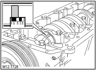
12. Using a special ruler, measure the width of the deformable gauges and determine the clearance in the connecting rod bearings:
13. If the used connecting rod bearings cannot provide the required clearance, the connecting rod journals must be ground to the next repair size and the appropriate repair bearings must be used.
14. Leave the liners that are considered good in their places, in the connecting rods and the roofs of the first and sixth cylinders.
15. Using a rag soaked in engine oil, wipe off all traces of the deformable gauge from the surface of the connecting rod journals.
16. Perform the operations described above on the remaining connecting rod journals.
17. After checking the connecting rod bearing clearances, discard the used connecting rod bolts.
Assembly
1. Lubricate the connecting rod journals and the connecting rod bearings that have been found to be in good condition with clean engine oil.
2. Install the bearings selected for use into the connecting rods and connecting rod caps, making sure that the bearings marked with the letter "S" are used as the upper bearings.
3. Lower the connecting rods onto the crankpins, paying attention to the correct position of the bearings.
4. After aligning the marks, install the connecting rod caps in their places.
5. Lubricate new connecting rod bolts with clean engine oil.
6. Screw in the new connecting rod bolts and tighten them:
- Stage 1 - 5 Nm.
- Stage 2 - 25 Nm.
- Step 3 - Using an angle torque wrench, tighten the bolts an additional 70°.
7. Wipe the bottom plate and the mating surface.
8. Install the bottom plate in place, screw in the bolts and tighten them evenly. Tightening torque 22 Nm.
Installation
1. Install the oil pump.
ENGINE TD6, REPAIR WORK, Oil pump.
Comments on this article