Removal
1. Remove the hydraulic lifters.
ENGINE TD6, REPAIR WORK, Hydraulic compensators.
Disassembly
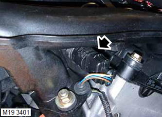
1. Disconnect the connector from the fuel pressure sensor.
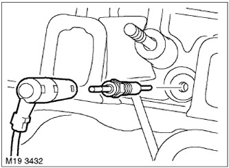
2. Disconnect the connectors from the glow plugs.
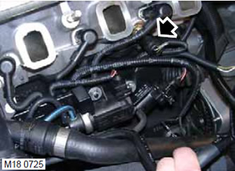
3. Disconnect the connector from the coolant temperature sensor.
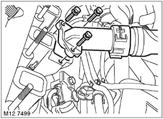
4. Remove the 3 bolts and coolant pipe from the cylinder head. Discard the gasket.
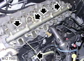
5. Unscrew the nuts and disconnect the fuel pipes from the fuel rail and from the fuel pump. Remove the fuel pipe support sleeve.
CAUTION: To prevent contamination, install plugs on open connectors.
6. Unscrew 3 bolts and remove the fuel rail.
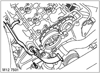
7. Remove the 2 bolts securing the heat shield and EGR system pipe to the exhaust manifold.
8. Remove the heat shield.
9. Remove the EGR pipe with the clamp.
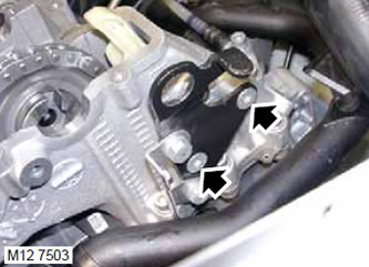
10. Unscrew the two bolts securing the rigging eye and remove the eye.
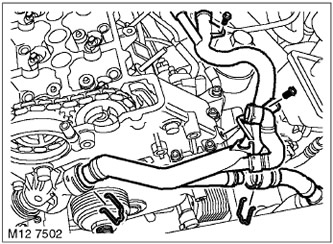
11. Loosen the clamp and disconnect the expansion tank hose from the cooling system pipe.
12. Unscrew the 2 bolts securing the cooling system tube.
13. Unscrew the clamp, disconnect the cooling system pipe from the thermostat housing and move it to the side.
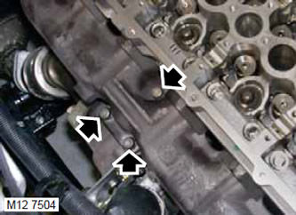
14. Remove the 3 bolts securing the turbocharger to the exhaust manifold. Discard the gasket.
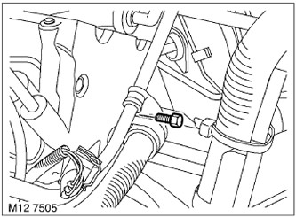
15. Loosen the bolt securing the vacuum hose support clamp and wire harness to the cylinder head.
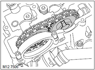
16. Remove the camshaft drive chain from the sprockets.
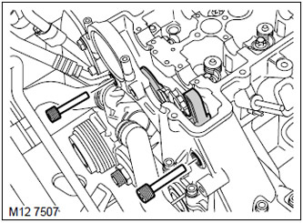
17. Remove and discard the timing chain tensioner clips.
18. Remove the chain guides. Access to the guide from the intake manifold side is improved with the cylinder head removed.
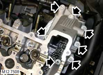
19. Unscrew the 7 bolts securing the cylinder head to the timing cover.
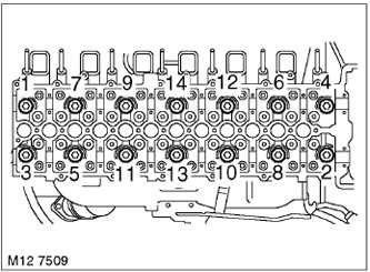
20. In the sequence shown, unscrew and dispose of the 14 cylinder head mounting bolts.
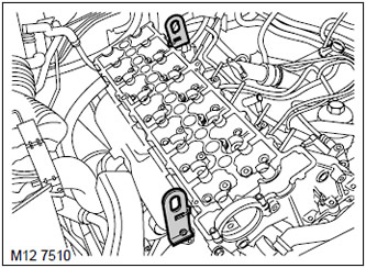
21. Install the lifting eyes on the cylinder head and secure them to it.
22. Put on the lifting chains, release the cylinder head from the pins and remove it. The protruding glow plugs should be protected from damage.
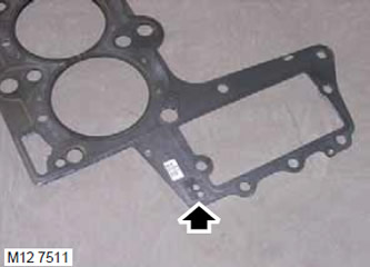
23. Determine the thickness of the gasket by the number of notches in it. Remove and dispose of the gasket.
Examination
1. Wipe the lower surface of the cylinder head, the upper surface of the cylinder block, the pins and the holes for them. If necessary, remove the remains of the sealant with a scraper made of hard wood. Do not allow the remains of the sealant to get into the oil supply channels, into the cooling system and into the threaded sockets.
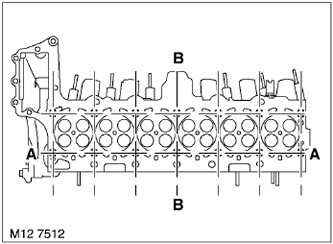
2. Using a straightedge and feeler gauge, check the deformation of the lower plane of the head in the directions shown in the figure.
TECHNICAL SPECIFICATIONS, Engine - Td6.
3. If the deformation values exceed the permissible values, replace the cylinder head. Milling of the lower plane of the cylinder head is not allowed.
4. If the connecting rod and piston group has not been replaced, a new gasket of the same thickness should be used. (with the same number of notches), as the previous one. If the connecting rod and piston group was replaced, then to select the correct thickness of the gasket, you need to measure the protrusion of the pistons.
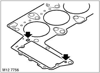
5. After making sure that the sealant strips on the gasket are not damaged, install the gasket onto the cylinder block.
Assembly
1. Lightly lubricate the new cylinder head bolts with engine oil.
2. Carefully place the cylinder head on the block so that the pins enter the sockets.
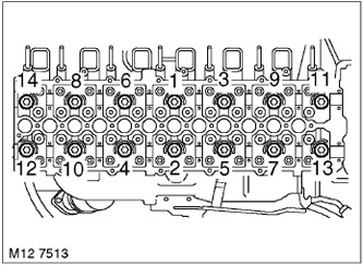
3. Install the cylinder head mounting bolts and tighten them in the specified sequence. Tightening torque 80 N·m. Loosen all bolts by half a turn and tighten them again. Tightening torque 50 N·m. Using an angle torque wrench, tighten all bolts in the specified sequence by 90° and then another 90°.
4. Tighten the cylinder head to timing cover bolts. Tightening torque 20 Nm.
5. Wipe the timing chain guides.
6. Position the chain guides so that the guide on the intake manifold side fits onto the lower clamp and tighten both new upper clamps. Tightening torque is 20 N·m.
7. Wipe the camshaft sprockets.
8. Place the camshaft drive chain onto the sprockets.
9. Wipe the turbocharger and the mating surface on the exhaust manifold.
10. Install the turbocharger on a new gasket and tighten its mounting bolts. Tightening torque 50 Nm.
11. Install the vacuum hose and wiring harness support clamps, tighten the bolt. Tightening torque is 10 N·m.
12. Wipe the cooling system pipes and mating surfaces.
13. Connect the cooling system pipe to the thermostat housing and secure it with a clamp.
14. Screw in the cooling system pipe mounting bolts and tighten them. Tightening torque 10 Nm.
15. Connect the hose to the expansion tank and secure it with a clamp.
16. Install the lifting eye and tighten the bolts. Tightening torque 25 Nm.
17. Wipe the exhaust gas recirculation pipe and the counter rest area.
18. Install the EGR pipe, heat shield, screw in the mounting bolts, but do not tighten them yet. After installing the EGR cooling heat exchanger, tighten the bolts. Tightening torque 25 Nm.
19. Wipe the cooling system hose and the mating surface.
20. Place the coolant hose on the new gasket and tighten the bolts. Tightening torque 8 Nm.
21. Install the fuel rail in place and tighten the mounting bolts. Tightening torque 24 N·m.
22. Install the high-pressure fuel pipes and support sleeve, tighten the nuts on the pipes. Tightening torque 20 N·m.
23. Connect the connector to the coolant temperature sensor.
24. Place the connectors on the glow plugs.
25. Connect the connector to the fuel pressure sensor.
Installation
1. Install hydraulic lifters.
ENGINE TD6, REPAIR WORK, Hydraulic compensators.
Comments on this article