Contents: Cylinder heads ⇩ Camshafts ⇩ Valves and hydraulic slack adjusters ⇩ Valve lever oil line ⇩ Cylinder head gasket ⇩ Fuel injectors ⇩ Camshaft cover ⇩ Camshaft Position Sensor (CMP) ⇩
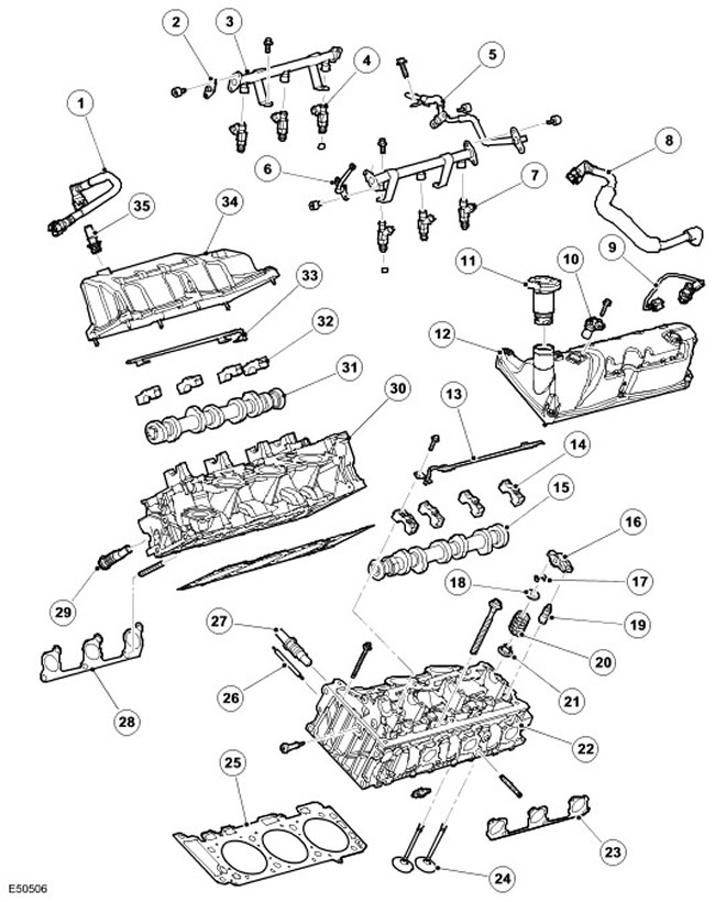
| Item name | Spare part catalog number | Description |
| 1 | - | Crankcase ventilation hose between the right-hand camshaft cover and the intake manifold |
| 2 | - | End cap |
| 3 | - | Right fuel rail |
| 4 | - | Left fuel injectors (3 pcs.) |
| 5 | - | Fuel supply line |
| 6 | - | Schrader valve |
| 7 | - | Right fuel injectors (3 pcs.) |
| 8 | - | Blow-off hose between left-hand camshaft cover and intake manifold |
| 9 | - | Electrically heated crankcase ventilation valve |
| 10 | - | Camshaft Position (CMP) Sensor |
| 11 | - | Oil filler cap |
| 12 | - | Left cylinder bank camshaft cover |
| 13 | - | Left valve lever oil line |
| 14 | - | Left cylinder bank camshaft bearing caps |
| 15 | - | Left camshaft |
| 16 | - | Valve lever |
| 17 | - | Sleeve |
| 18 | - | Valve spring plate |
| 19 | - | Hydraulic clearance adjuster |
| 20 | - | Valve spring |
| 21 | - | Valve stem seal |
| 22 | - | Left cylinder head |
| 23 | - | Left exhaust manifold gasket |
| 24 | - | Valves |
| 25 | - | Cylinder head gasket |
| 26 | - | Plug/volume reduction valves |
| 27 | - | Timing chain tensioner |
| 28 | - | Right exhaust manifold gasket |
| 29 | - | Camshaft timing chain tensioner |
| 30 | - | Right cylinder head |
| 31 | - | Right camshaft |
| 32 | - | Bearing caps of the camshaft of the right bank of cylinders |
| 33 | - | Right valve lever oil line |
| 34 | - | Right cylinder bank camshaft cover |
| 35 | - | Crankcase ventilation valve |
Cylinder heads
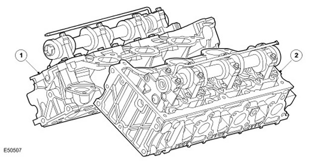
| Item name | Spare part catalog number | Description |
| 1 | - | Right cylinder head |
| 2 | - | Left cylinder head |
The cylinder head with intake and exhaust ports on different sides has dual valves and a central combustion chamber for spark plugs. The design of the intake ports provides swirl and control of intake velocity. This improves combustion and thereby improves fuel economy, performance and reduces toxicity of exhaust emissions.
The left and right cylinder heads are identical castings.
Camshafts
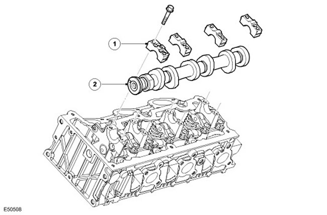
| Item name | Spare part catalog number | Description |
| 1 | - | Bearing cap |
| 2 | - | Camshaft |
One camshaft on each cylinder bank is supported by a camshaft housing; the hole for it is bored in the cylinder head. The camshafts are fixed with a flange, which also controls the axial clearance.
The left camshaft contains a timing disc which, together with the crankshaft position (CMP) sensor, provides engine position detection.
Valves and hydraulic slack adjusters
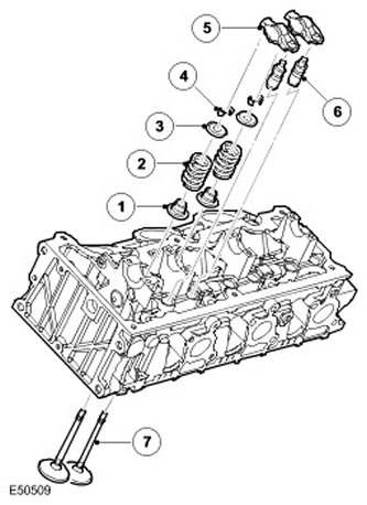
| Item name | Spare part catalog number | Description |
| 1 | - | Valve stem seal |
| 2 | - | Valve spring |
| 3 | - | Valve spring plate |
| 4 | - | Valve spring plate key |
| 5 | - | Valve lever |
| 6 | - | Hydraulic clearance adjuster |
| 7 | - | Valve |
Valve springs are made of spring steel and are cylindrical in shape. The lower end of each spring rests on a flange of the spring plate, which has a built-in valve stem seal. The upper end of the spring is held in place by a spring plate, which is secured to the upper end of the valve stem by conical crackers. The conical crackers have a series of grooves and projections along the inside diameter that fit into grooves and projections in the tops of the valve stems.
The valve seats and guide bushings are fixedly seated in the cylinder head.
The valves are actuated by roller levers and hydraulic lash adjusters via camshaft lobes. When a camshaft lob presses on the top of the roller lever mechanism, the corresponding valve drops, opening the intake or exhaust port. This actuation method reduces friction in the valve timing mechanism.
The hydraulic lash adjuster housing contains a plunger and two chambers for supplying oil and pressurized oil. Pressurized oil is supplied to the lash adjusters through the main oil galleries in the cylinder head and through an opening in the side of the lash adjuster housing. The oil passes into the lash adjuster feed chamber and then into a separate discharge chamber through a one-way ball valve.
The flow of oil from the discharge chamber is determined by the clearance between the outer housing and the central plunger of the lash adjuster. Oil is forced to the upper side of the plunger whenever the lash adjuster moves. The downward force acting on the plunger forces a corresponding amount of oil into the lash adjuster housing. When the downward force from the camshaft and tappet disappears (that is, after the approach side of the camshaft cam has passed), the oil pressure forces the lash adjuster plunger to rise again. This pressure is not enough to operate the valve effectively, but it eliminates the gap between the tappet and the top of the valve stem.
Valve lever oil line
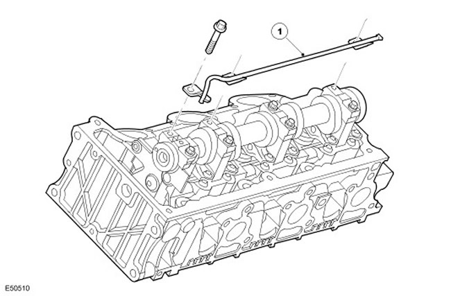
| Item name | Spare part catalog number | Description |
| 1 | - | Valve lever oil line |
The rocker arm oil line is located at the top of each camshaft and is attached with two bolts to the front and rear camshaft bearing caps. Oil is supplied by a tube through an oil gallery in the cylinder head and distributed to the rocker arms through adjacent spray holes in the tube.
Cylinder head gasket
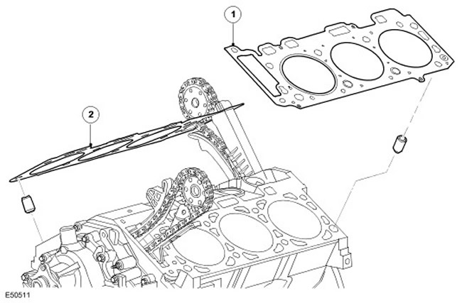
| Item name | Spare part catalog number | Description |
| 1 | - | About the left cylinder head gasket |
| 2 | - | Right cylinder head gasket |
The multi-layer steel cylinder head gasket has different coolant passages for each cylinder, which ensures uniform fluid flow.
Fuel injectors
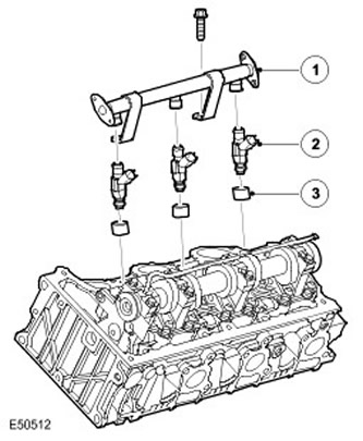
| Item name | Spare part catalog number | Description |
| 1 | - | Fuel rail |
| 2 | - | Nozzle |
| 3 | - | Adapter |
Fuel injectors are mounted in each of two fuel rails, one for each cylinder head. The injectors and solenoids are controlled by the ECM. Each injector nozzle is secured to the cylinder head by an adapter. The connection between each injector and the fuel rail is sealed with an O-ring. The injectors deliver fuel to the rear of the intake valves. For more information, refer to Electronic Engine Controls (303-14A Electronic Engine Controls -4.0L)
Camshaft cover
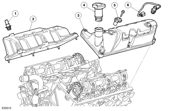
| Item name | Spare part catalog number | Description |
| 1 | - | Crankcase ventilation valve |
| 2 | - | Right cylinder bank camshaft cover |
| 3 | - | Left cylinder bank camshaft cover |
| 4 | - | Oil filler cap and extension |
| 5 | - | Camshaft Position Sensor (CMP) |
| 6 | - | Electrically heated crankcase ventilation valve |
The camshaft covers are made of thermoplastic. The left cover has a hole located directly above the camshaft timing disk for installing the crankshaft position sensor. The left cover also contains an opening for the oil filler neck.
Camshaft Position Sensor (CMP)
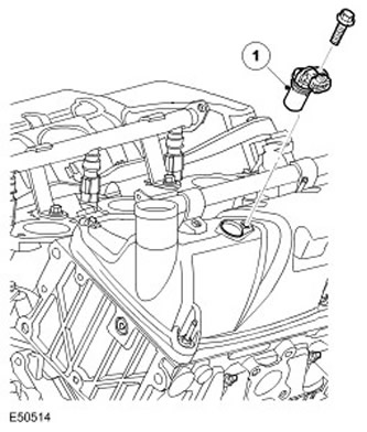
| Item name | Spare part catalog number | Description |
| 1 | - | CMP sensor |
The CMP sensor is mounted in the front of the left bank camshaft cover. The sensor is an electromagnetic sensor that generates a signal to the ECM containing information about the position of the camshaft. For more information, refer to Electronic Engine Controls (303-14A Electronic Engine Controls - 4.0L)
The timing disc for the camshaft position sensor is mounted at the front of the left-hand cylinder bank camshaft. A flat machined surface near the front of both camshafts allows them to be locked when adjusting the valve timing.
Comments on this article