Contents: Dismantling ⇩ Installation ⇩
Dismantling
1. Disconnect the negative battery terminal.
2. Drain the coolant from the engine.
COOLING SYSTEM: Td4 engine, ADJUSTMENTS, Draining coolant, flushing the system and filling.
3. Remove the hydraulic lifters.
ENGINE - Td4, Inlet and outlet camshafts, Hydraulic compensators, engine kit.
4. Support the engine by placing a jack with a wooden block as a spacer under the pan.
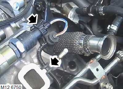
5. Disconnect the connector from the fuel pressure sensor.
6. Remove the rubber bushing of the wiring harness from the cylinder head.
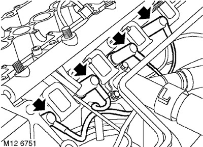
7. Disconnect the connectors from the glow plugs.
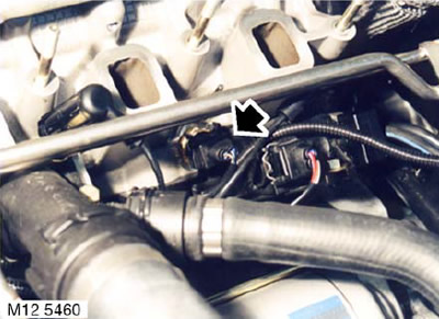
8. Disconnect the connector from the coolant temperature sensor.
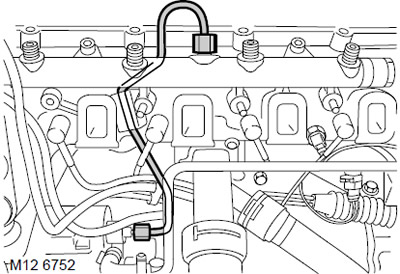
9. Loosen the nuts and disconnect the fuel pipes from the fuel rail and fuel pump. Assemble the fuel pipe support bushings.
CAUTION: Always plug the fittings and holes to protect the system from dirt.
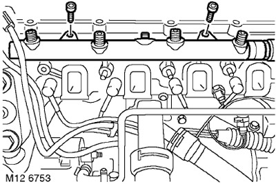
10. Unscrew 2 bolts and remove the fuel rail.
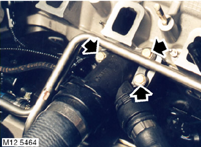
11. Remove the three bolts and move the coolant pipe away from the cylinder head. Discard the gasket.
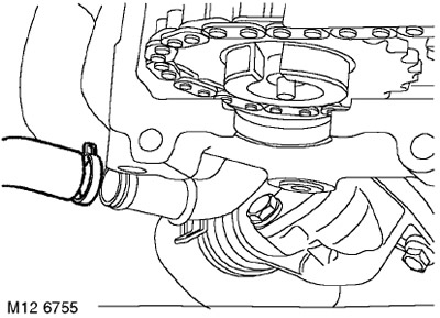
12. Loosen the clamp and disconnect the expansion tank hose from the cooling system distribution pipe.
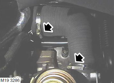
13. Loosen the clamps and remove the hose from the turbocharger outlet pipe.
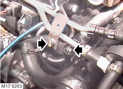
14. Unscrew the bolt securing the fuel rail to the support bracket.
15. Loosen the bolt securing the turbocharger outlet hose to the support bracket.
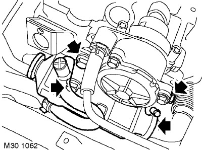
16. Loosen the clamp securing the exhaust gas recirculation tube to the heat exchanger and remove the clamp from the heat exchanger.
17. Unscrew the three bolts securing the exhaust gas cooling heat exchanger (recirculation system) to the cylinder head and to the eye.
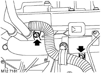
18. Loosen the bolt securing the turbocharger outlet hose to the cooling system distribution pipe.
19. Loosen the bolt securing the turbocharger outlet hose to the bracket on the exhaust manifold.
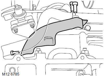
20. Remove the three bolts securing the heat shield to the cooling system distribution pipe.
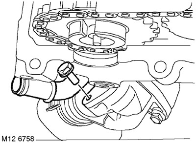
21. Loosen the bolt, remove the coolant pipe from the thermostat housing and discard the gasket.
22. Remove the heat shield.
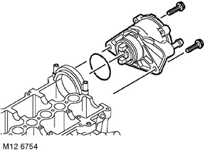
23. Remove and discard the 2 vacuum pump mounting screws.
24. Remove the vacuum pump and set it aside. Discard the gasket.
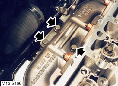
25. Remove the 3 bolts securing the turbocharger to the exhaust manifold. Discard the gasket.
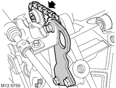
26. Unscrew the bolt securing the power steering tube clamp to the eye.
27. Unscrew the two bolts and remove the eye.
[The original article is located on the website: www.lrman.ru]
28. Remove the camshaft drive chain from the sprockets.
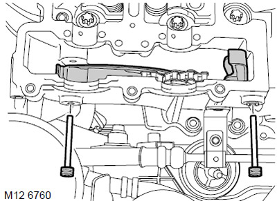
29. Remove and discard the timing chain tensioner clips.
30. Remove the chain guides.
Access to the guide from the intake side will be better with the cylinder head removed.
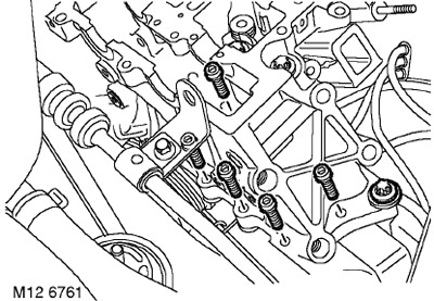
31. Remove 5 Allen bolts and one cylinder head mounting bolt that goes through the front cover (timing drive cover).
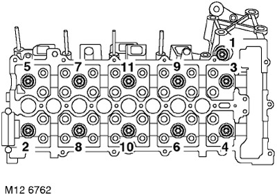
32. In the sequence shown, unscrew and dispose of the 11 cylinder head mounting bolts.
33. With the help of a partner, remove the cylinder head.
Care must be taken not to damage the protruding glow plugs.
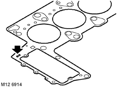
34. Determine the thickness of the gasket by the number of notches in it. Remove and dispose of the gasket.
Installation
1. Clean the cylinder head, cylinder block, pins and pin holes. If necessary, remove any remaining sealant with a hardwood scraper. Make sure that no sealant remains in the oil or water passages or in the threaded seats.
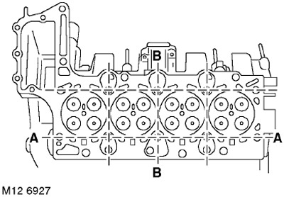
2. Using a straightedge and feeler gauge, check the deformation of the lower plane of the head in the directions shown in the figure.
TECHNICAL SPECIFICATIONS, Engine - Diesel Td4.
3. If the curvature of the lower plane exceeds the maximum permissible value, the cylinder head must be replaced. Milling of the lower plane of the head is not allowed.
4. The new gasket must have the same thickness (number of notches) as the previous one, unless new pistons and connecting rods were installed. If the connecting rod and piston group was replaced, then to select the correct gasket thickness, you need to measure the piston protrusion.
ENGINE - Td4, ADJUSTMENTS, Checking piston protrusion with cylinder head removed.
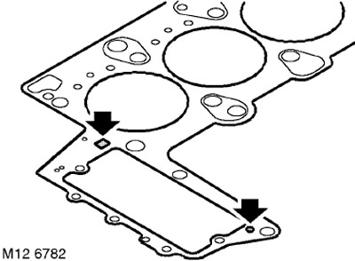
5. After making sure that the sealant strips on the gasket are not damaged, install the gasket onto the cylinder block.
6. Lightly coat the 12 new cylinder head bolts with engine oil.
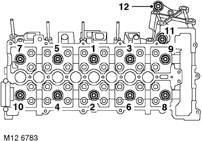
7. With the help of a partner, install the cylinder head and tighten the 11 bolts in the sequence shown to a torque of 80 Nm. The long bolt should be in position marked 11 as shown in the illustration. Loosen all bolts by half a turn and retighten them. Tightening torque is 50 Nm. Using an angle torque wrench, tighten all bolts in the sequence shown by 90° and then another 90°.
8. Tighten the last bolt, 41 mm long and located in position 12, to a torque of 110 Nm.
9. Tighten the cylinder head to timing cover bolts. Tightening torque 5 Nm.
10. Wipe the timing chain guides.
11. Position the chain guides so that the guide on the intake manifold side fits onto the lower clamp and tighten both new upper clamps. Tightening torque is 20 Nm.
12. Wipe the camshaft sprockets.
13. Place the camshaft drive chain onto the sprockets.
14. Install the eye and tighten the bolts to 20 Nm.
15. Tighten the power steering tube mounting bolt to the eye to a torque of 10 Nm.
16. Install the turbocharger on a new gasket and tighten its mounting bolts. Tightening torque 45 Nm.
17. Clean the vacuum pump and mating surfaces from dirt.
18. Install a new seal on the vacuum pump, install the vacuum pump and tighten the new mounting bolts to 22 Nm.
19. Wipe the cooling system distribution pipe and mating surfaces.
20. Install the heat shield.
21. Install a new seal on the coolant distribution pipe, install the pipe on the thermostat housing and tighten the bolt to 8 Nm.
22. Tighten the heat shield mounting bolts. Tightening torque 8 Nm.
23. Install the EGR heat exchanger and fuel rail and tighten the mounting bolts. Tightening torque 25 Nm.
24. Put on the EGR pipe clamp and tighten the screw.
25. Route the turbocharger outlet hose and secure it. Tightening torque for M8 bolts is 25 Nm, for M6 bolts - 10 mm.
26. Screw in the fuel rail mounting bolt to the support bracket and tighten it. Tightening torque 10 Nm.
27. Install the turbocharger air outlet hose and tighten the clamps.
28. Connect the hose to the expansion tank and secure it with a clamp.
29. Wipe the cooling system hose and the mating surface.
30. Install a new gasket on the coolant pipe and tighten the bolts to 8 Nm.
31. Install the fuel rail in place and tighten the mounting bolts. Tightening torque 24 Nm.
32. Install the high-pressure fuel pipe and support sleeve, tighten the nut on the pipe. Tightening torque 30 Nm.
33. Connect the connector to the coolant temperature (ECT) sensor.
34. Connect the connectors to the spark plugs.
35. Connect the connector to the fuel pressure sensor.
36. Insert the rubber bushing of the wiring harness into the cylinder head.
37. Install hydraulic lifters.
ENGINE - Td4, Inlet and outlet camshafts, Hydraulic compensators, engine kit.
38. Connect the negative battery terminal.
39. Fill the engine with coolant.
COOLING SYSTEM: Td4 engine, ADJUSTMENTS, Draining coolant, flushing the system and filling.
Comments on this article