Contents: Removal ⇩ Installation ⇩
Removal
1. Disconnect the battery.
2. Remove the hood (see "Body").
3. Drain the coolant.
4. Remove the air filter (see "Fuel system").
5. Disconnect the crankcase ventilation valve and hose from the valve cover and secure them to the side.
6. Remove the high-pressure pipes from the injectors and fuel injection pump.
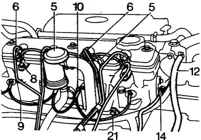
7. Disconnect the drain tube from the injectors.
8. Remove the injectors and sealing washers.
9. Remove the glow plug wires.
10. Remove the glow plugs.
11. Disconnect the radiator hose from the thermostat.
12. Disconnect the bypass hose from the thermostat.
13. Disconnect the water pump hose from the thermostat.
14. Disconnect the coolant temperature sensor wire.
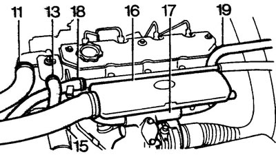
15. Disconnect the charge air cooler hose from the intake manifold.
16. Remove the intake manifold (see "Intake and exhaust systems").
17. Remove the exhaust manifold together with the turbocharger (see "Intake and exhaust systems").
18. Disconnect the heater hoses from the water pump and secure them to the side.
19. Disconnect the heater hose at the rear of the head.
20. Remove the mounting bolt that supports the air filter bracket struts.
21. Remove the wiring support bracket mounting bolt.
22. Remove the rear engine lift bracket, note the location of the spacers and clips holding the engine and gearbox ventilation hoses and wiring.
23. Remove the valve cover.
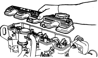
24. Loosen the rocker arm axle bolts and nuts and remove the axle assembly.
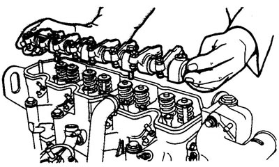
25. Remove the push rods and number them.
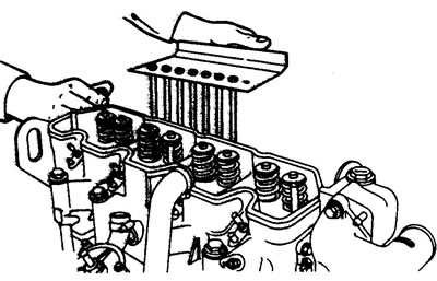
26. Remove the caps from the ends of the valves.
27. Loosen and then completely remove the cylinder head bolts.
28. Remove the cylinder head and gasket
Installation
29. Clean the block mating surfaces.
30. Select a gasket of the required thickness.
Please note: The thickness of the gasket is identified by the number of holes on the right edge of the gasket, there are three types of gaskets in total. Install only the same thickness gasket as was installed previously.
31. Place the gasket on the block with the TOP mark facing up, and the identification holes should be on the right.
32. Clean the mating surface of the cylinder head.
33. Place the head on the block along the guide pins.
Note: reinstallation (tightening) of the cylinder head mounting bolts is allowed no more than five times.
[Original article on the web portal: www.lrman.ru]
34. Lightly lubricate the bolt threads with engine oil, install the bolts as shown in the figure. Bolt size:
- M10x147 mm - positions 3, 5, 12 and 13;
- M12x140 mm - positions 1, 2, 7, 8, 9, 10, 15, 16, 17 and 18;
- M12x100 mm - positions 4, 6, 11 and 14.
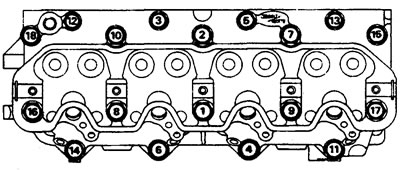
35. Tighten all bolts by hand.
36. Tighten the bolts to 40 Nm in the order shown in the figure.
37. Install the LRT-12-007 angle gauge on the handle.
38. Make a marker from wire and attach it to the rocker arm axle bolt.
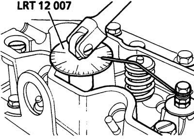
39. In the order shown in the figure, tighten all bolts by 60 degrees.
40. Tighten the bolts again by 60 degrees.
41. Tighten the long bolts (M12x140 mm, 10 pieces) another 20 degrees.
Note: Remember to change the position of the marker each time.
Caution: Failure to tighten the bolts correctly may result in damage to the cylinder head.
42. Install the caps on the end of the valves.
43. Install the push rods in place.
44. Install the rocker arm shaft and tighten the fasteners in several steps to the recommended torque.
45. Install the valve cover.
46. Tighten the valve cover fastener to the recommended torque.
Caution: Do not reuse the valve cover gasket more than 5 times.
47. Install the removed parts (item 22-1).
Comments on this article