- Cylinder head and valves
- Camshafts
- Cylinder head gasket
- glow plugs
- fuel injectors
- Head Temperature Sensor (CHT)
- High pressure fuel manifold
- Intake manifold
- An exhaust manifold
- Camshaft housing
- Valve clearance hydraulic compensator
- Camshaft position sensor (SMR)
- Camshaft and engine cover
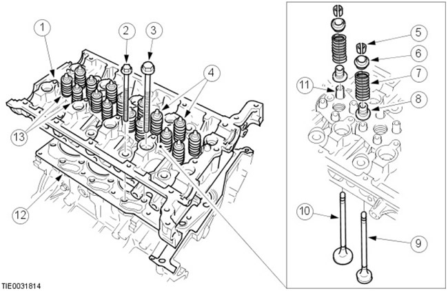
Cylinder head and valves
| Pos. | spare part no | Name | |
| 1 | - | cylinder head | |
| 2 | - | External cylinder head bolt (8 pcs.) | |
| 3 | - | Cylinder head inner bolt (10 pieces.) | |
| 4 | - | intake valves (16 pcs.) | |
| 5 | - | Valve crackers (32 pcs.) | |
| 6 | - | Spring holder (16 pcs.) | |
| 7 | - | valve spring (16 pcs.) | |
| 8 | - | Valve stem seal (16 pcs.) | |
| 9 | - | Exhaust valve (8 pcs.) | |
| 10 | - | Inlet valve (8 pcs.) | |
| 11 | - | valve guide (16 | PC.) |
| 12 | - | Cylinder head gasket | |
| 13 | - | valve assembly |
The cylinder head is die-cast aluminum. The presence of four valves per cylinder provides improved cylinder supply, a compact combustion chamber and a vertical arrangement of fuel injectors, which creates optimal distribution of fuel in the combustion chamber.
The cylinder head is fastened to the cylinder block by eighteen recessed (to reduce deformation) bolts. The 8 outer cylinder head bolts are shorter than the inner ones and are located under the camshafts: 4 under the intake camshaft and 4 under the exhaust cam. 2 hollow pins ensure the alignment of each cylinder head with the cylinder block.
The cylinder head has four holes per cylinder (two exhaust and two intake), the arrangement of which corresponds to the arrangement of the cylinders. One of the inlet ports is screwed and acts as a swirl channel, and the other - the tangential port - is located on the side and is responsible for supplying the combustible mixture.
NOTE: The cylinder head cannot be remachined.
All valves have powder metal seats and guide bushings. In both intake and exhaust valves, single valve springs are held in place by bushings, valve discs, and spring seats. The valve stem seals are built into the spring seats.
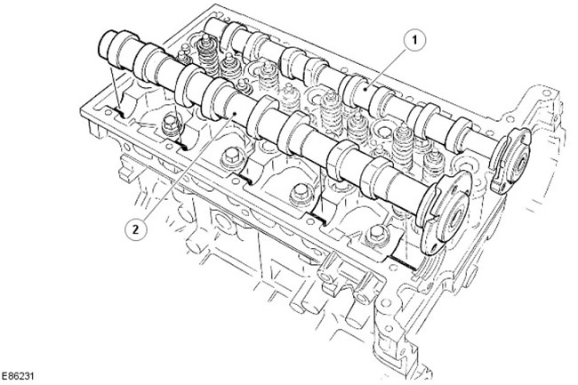
Camshafts
| Pos. | spare part no | Name |
| 1 | - | intake camshaft |
| 2 | - | exhaust camshaft |
Hollow camshafts with pressed-in powder metal lugs; at the front, their surface is machined to fit the sprocket. The camshafts are fixed in the cylinder head by the camshaft housing. Impulse wheel machined at the rear of the intake camshaft provides a signal for the camshaft position sensor (CMP), with which the ECM determines the position of the camshaft relative to the crankshaft.
For more information, see the chapter: Electronic controls (303-14 Electronic Controls - Diesel Engine ID4 2.4L, Description and Operation).
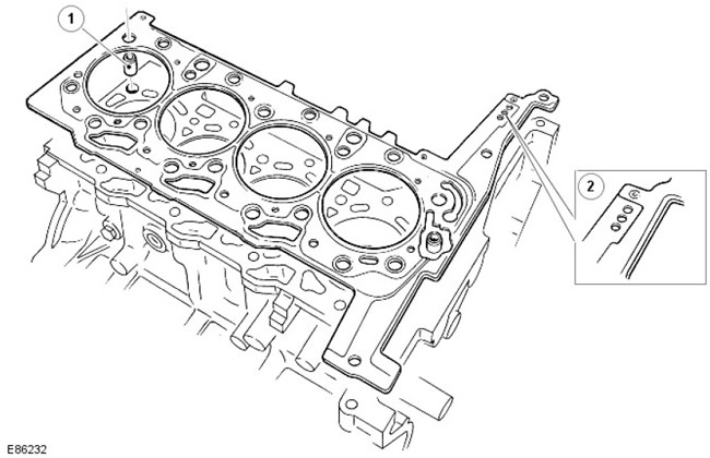
Cylinder head gasket
| Pos. | spare part no | Name |
| 1 | - | Mounting sleeve (2 pcs.) |
| 2 | - | Identification holes |
Cylinder head gasket 4-layer steel; Gaskets are available in 3 thicknesses. The selection of the required size depends on the maximum piston protrusion. The thickness of the gasket is determined by the number of holes in the front of the gasket.
The cylinder block has two dowel sleeves to center the cylinder head gasket.
NOTE: When replacing the cylinder head gasket, use only a new gasket with the same identification mark. When installing new pistons or connecting rods, measure the maximum piston protrusion and select the appropriate gasket.
Damage to the gasket or mating surfaces of the head and cylinder block will result in leaks and should therefore be avoided. Before installing a new gasket, it is important to ensure that there is no dirt between the layers of the gasket.
Glow plugs
| Pos. | spare part no | Name |
| 1 | - | Power wire |
| 2 | - | glow plugs (4 things.) |
The glow plugs are centrally mounted on the intake valve side, between the two ports on each cylinder.
For more information, see chapter: Glow Plug System (303-07 Glow plug system - Diesel engine ID4 2.4L, Description and principle of operation).
Injectors
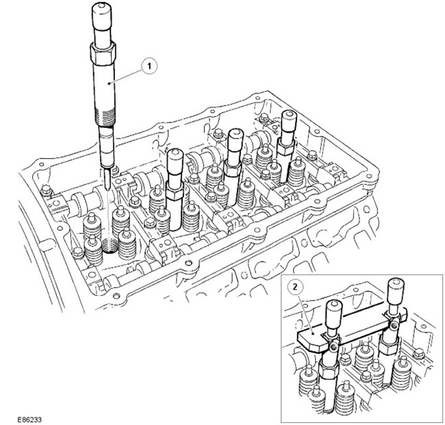
| Pos. | spare part no | Name |
| 1 | - | Nozzle |
| 2 | - | Nozzle centering tool |
4 electronic fuel injectors are centrally located (1 above each cylinder) and are attached to the cylinder head with a nut.
Fuel injectors inject the required amount of fuel in accordance with the current engine load into the combustion chambers. To ensure optimal fuel injection timing and the exact amount of injected fuel, special fuel injectors with a hydraulic servo system and an electric actuator are used (solenoid valve).
The injectors are controlled directly by the engine control unit (ECM).
For more information, see the chapter: Fuel supply and controls (303-04A Fuel supply and controls - ID4 2.4L diesel engine, Description and operation), Electronic controls (303-14 Electronic Controls - Diesel Engine ID4 2.4L, Description and Operation).
Head Temperature Sensor (CHT)
The CHT sensor is located at the center rear of the cylinder head (from the gearbox side). The sensor measures the cylinder head temperature, not the coolant temperature.
The CHT sensor affects the following functions:
- amount of injected fuel
- start of fuel injection
- idling speed
- preheating operation
- EGR system
For more information, see the chapter: Electronic controls (303-14 Electronic Controls - Diesel Engine ID4 2.4L, Description and Operation).
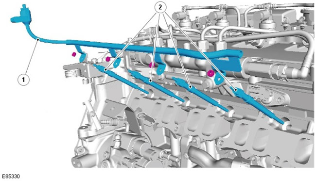
High pressure fuel manifold
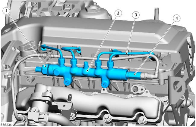
| Pos. | spare part no | Name |
| 1 | - | Fuel pressure sensor |
| 2 | - | High pressure fuel manifold |
| 3 | - | High pressure fuel lines (between fuel rail and injectors) |
| 4 | - | Pressure limiting valve |
fuel manifold (common rail system, automatic telephone exchange) made from forged steel. It serves to store high pressure fuel and prevent pressure fluctuations in the high pressure system.
The injection pump delivers fuel through the high pressure fuel line to the fuel manifold. The fuel is then sent through four injector fuel lines, which are of the same length, to the individual fuel injectors.
The pressure relief valve opens at a fuel pressure of approximately 2000 bar. It acts as a fuse in case of failure of the high pressure system, preventing damage due to overpressure.
NOTE: The pressure relief valve is maintenance free. In the event of a trip, it must be replaced, since its further tightness is not guaranteed.
Pressure relief valve actuation is detected by the ECM and an appropriate DTC is generated (DTC) and the warning lamp for malfunctioning emission control systems is activated (MIL).
For more information, see the chapter: Fuel supply and controls (303-04A Fuel supply and controls - ID4 2.4L diesel engine, Description and operation), Electronic controls (303-14 Electronic Controls - Diesel Engine ID4 2.4L, Description and Operation).
Intake manifold
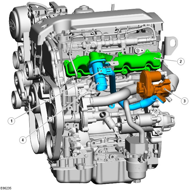
| Pos. | spare part no | Name |
| 1 | - | Mass Air Flow/Intake Air Temperature Sensor (MAF/IAT) |
| 2 | - | Intake manifold |
| 3 | - | EGR valve |
| 4 | - | Exhaust valve EGR assy |
The plastic intake manifold is mounted on the left side of the cylinder head and has a connector to connect the EGR valve outlet pipe. The EGR outlet pipe also houses the MAF/IAT sensor used by the ECM to calculate the amount of air entering the engine.
For more information, see the chapter: Electronic controls (303-14 Electronic Controls - Diesel Engine ID4 2.4L, Description and Operation).
An exhaust manifold
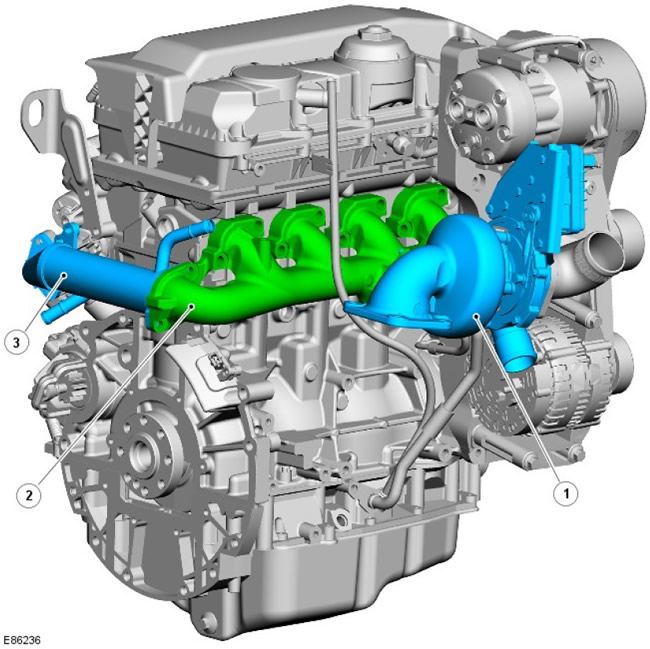
| Pos. | spare part no | Name |
| 1 | - | Turbocharger assembly |
| 2 | - | An exhaust manifold |
| 3 | - | EGR cooler |
The cast iron exhaust manifold is attached to the cylinder head with 8 studs and nuts. Two metal gaskets are used as a seal between the manifold and the cylinder head.
The flange at the front of the manifold is for connecting the turbocharger. The turbocharger is attached to the flange with 3 bolts and sealed with a metal gasket.
The second flange, located on the back of the manifold, is for attaching the EGR cooler. The cooler flange is attached to the manifold with 2 bolts. There is no gasket between the EGR cooler and the exhaust manifold.
The EGR system directs exhaust gases to the intake manifold for use in the combustion process. The main effect of this is to lower the temperature in the combustion chamber, which in turn reduces nitrogen oxide emissions (NOx).
For more information, see the chapter: Emissions reduction (303-08 Emission Control - ID4 2.4L Diesel Engine, Description and Operation).
Camshaft housing
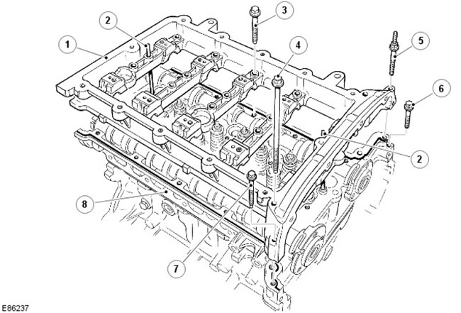
| Pos. | spare part no | Name |
| 1 | - | Camshaft housing |
| 2 | - | Centering pin |
| 3 | - | Bolt (20 pcs.) |
| 4 | - | Bolt (2 pcs.) |
| 5 | - | Hairpin |
| 6 | - | Bolt |
| 7 | - | Bolt |
| 8 | - | cylinder head |
The aluminum camshaft housing is located on the cylinder head and is secured with a pin and 24 bolts. Two centering studs are designed for precise installation of the housing on the cylinder head.
Hydraulic gap compensator
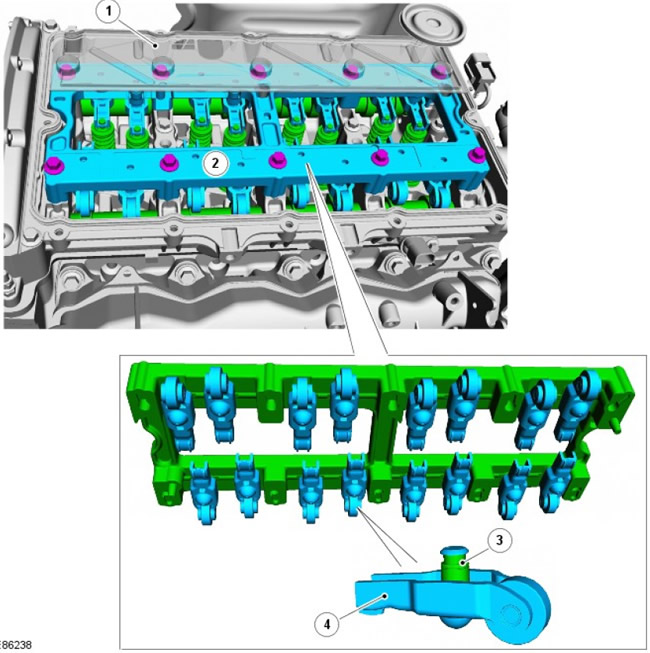
| Pos. | spare part no | Name |
| 1 | - | Oil deflector plate |
| 2 | - | aluminum support |
| 3 | - | Hydraulic gap compensator (16 pcs.) |
| 4 | - | Rocker arms (16 pcs.) |
The valves are actuated by roller rocker arms and hydraulic lash adjusters via camshaft lobes. The gap adjusters are built into the rocker arms, and the assembly itself is located inside the camshaft housing. When the camshaft cam presses on the top of the lever roller mechanism, the corresponding valve is lowered, opening the intake or exhaust port. This drive method reduces friction in the valve train.
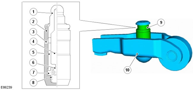
| Pos. | spare part no | Name |
| 1 | - | Plunger cover |
| 2 | - | Housing for hydraulic lash adjuster |
| 3 | - | Oil inlet |
| 4 | - | reservoir chamber |
| 5 | - | Pusher |
| 6 | - | Locking ball |
| 7 | - | injection chamber |
| 8 | - | plunger spring |
| 9 | - | Hydraulic gap compensator |
| 10 | - | rocker |
The body of hydraulic lash adjusters contains a plunger and two chambers for supplying oil and pressurized oil. Pressurized oil is supplied to the lash adjusters through the main oil galleries in the cylinder head and through an opening on the side of the lash adjuster housing. Oil flows into the lash adjuster feed chamber and then into a separate pressure chamber through a one-way ball valve.
The flow of oil from the pressure chamber is determined by the gap between the outer housing and the central plunger of the gap adjuster. Oil is supplied to the top side of the plunger whenever the lash adjuster is moved. The downward force acting on the plunger forces a corresponding amount of oil into the lash adjuster housing. When the downward force from the camshaft and pushrod disappears (i.e. after the incoming side of the camshaft cam is passed), the oil pressure causes the lash adjuster plunger to rise again. This pressure is not enough to operate the valve effectively, but eliminates the gap between the pushrod and the top of the valve stem.
Camshaft position sensor (SMR)
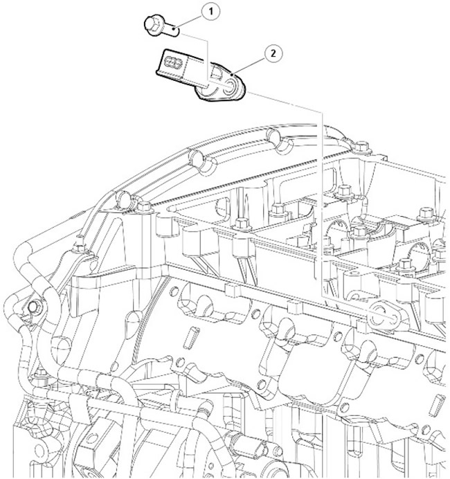
| Pos. | spare part no | Name |
| 1 | - | Bolt |
| 2 | - | CMP sensor (camshaft position) |
The CMP sensor is located on the left side of the cylinder head towards the rear. The tip of the sensor protrudes above the head of the block to monitor the rotation of the pulse wheel on the intake camshaft. The CMP sensor is a Hall sensor.
The ECM uses the signal from the CMP sensor to determine the position of the engine. Once this is set, the ECM can activate the correct injector to inject fuel into the cylinder when the piston is at TDC for injection.
The CMP sensor is used by the ECM at engine start to synchronize the ECM with the CKP sensor signal. The ECM does this by using the CMP sensor signal to identify cylinder #1 in order to ensure proper injection timing. Once the ECM advances the injection, the CMP sensor signal is no longer used.
For more information, see the chapter: Electronic controls (303-14 Electronic Controls - Diesel Engine ID4 2.4L, Description and Operation).
Cylinder head cover and engine cover
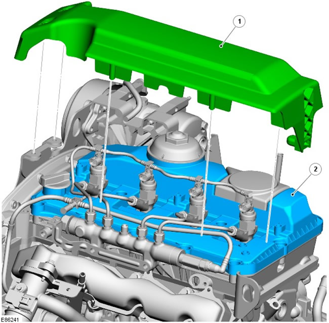
| Pos. | spare part no | Name |
| 1 | - | Engine cover |
| 2 | - | Camshaft cover |
Comments on this article