Contents: Cylinder block ⇩ Piston cooling nozzles ⇩ Connecting rods and pistons ⇩ Rear Oil Seal Holder ⇩ Crankshaft Position Sensor (CKP) ⇩ Starter ⇩ Generator ⇩ Coolant pump and vacuum pump ⇩ Power steering pump ⇩ High pressure fuel pump ⇩ Coolant distribution manifold ⇩
The cylinder block consists of the following main elements:
- Cylinder block
- Piston cooling nozzles
- Rear oil seal and crankshaft holder
- Connecting rods and pistons
- Crankshaft Position Sensor (CKP)
- Starter
- Generator
- Coolant pump and vacuum pump
- Power steering pump
- High pressure fuel pump
- Coolant distribution manifold
Cylinder block
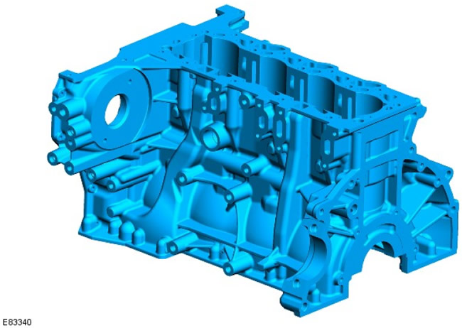
The cylinders and crankcase are housed in a cylinder block, which is a hollow monoblock construction made of grey cast iron. This design requires less material than a traditional cast iron cylinder block, reducing the weight and length of the engine.
The cylinders are bored directly into the cylinder block.
Three different cylinder diameters are used in the production of cars. This allows for very precise adjustment of the clearances between the pistons and cylinders.
The filter on the turbocharger inlet oil line is installed on the neck 1; it prevents foreign particles from the engine from entering the turbocharger and damaging the bearings.
Piston cooling nozzles
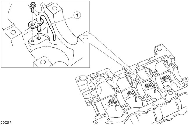
| Pos. | Spare part number | Name |
| 1 | - | Piston cooling nozzle |
The nozzle located in the cylinder block provides lubrication and cooling of the piston and piston pin. These nozzles spray oil into the piston, after which the oil, flowing through the internal wave-shaped channel, helps to cool the piston head.
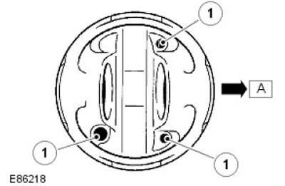
| Pos. | Spare part number | Name |
| A | - | Front of the engine |
| 1 | - | Oil cooling system channels |
Oil is supplied via the main oil line and channels in the cylinder block to all major moving parts of the engine. Oil is supplied to the main bearings of the crankshaft, and through the shaft bores to the connecting rod bearings.
Connecting rods and pistons
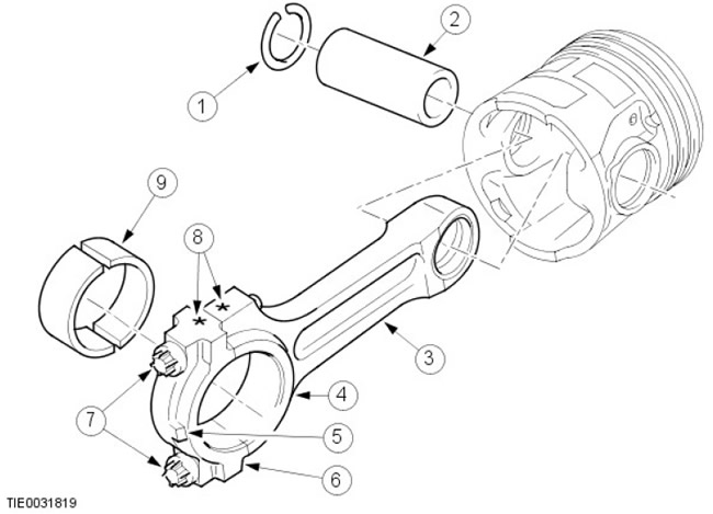
| Pos. | Spare part number | Name |
| 1 | - | Retaining ring |
| 2 | - | Piston pin |
| 3 | - | Connecting rods |
| 4 | - | Connecting rod bearing shell |
| 5 | - | Performance |
| 6 | - | Bearing cap |
| 7 | - | Bolts |
| 8 | - | Identification |
| 9 | - | Bearing insert |
The connecting rods are made of high-strength steel. Selectively selected aluminum-tin split plain bearings are used as connecting rod bearings. The connecting rod bearing has a special coating that allows the bearing to withstand a greater load and increases its service life.
There are 3 different connecting rod lengths available. For identification purposes, the connecting rod and bearing cap are marked with an identification code.
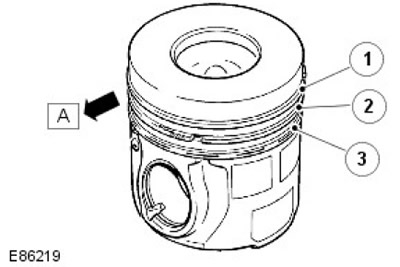
| Pos. | Spare part number | Name |
| A | - | Front of the engine |
| 1 | - | Upper compression ring |
| 2 | - | Lower compression ring |
| 3 | - | Oil scraper ring |
The pistons are made of aluminum alloy and are equipped with three rings. The intake air flow swirls in the combustion chamber. Turbulent movement promotes the formation of the fuel-air mixture and its complete combustion. In addition, the piston head has grooves for oil, improving cooling (for more information, see the section on piston cooling nozzles).
When installing the pistons, make sure that all arrows on the piston heads point towards the front of the engine.
Each piston is mounted on a piston pin, which is installed in an aluminum-tin bushing in the connecting rod.
Rear Oil Seal Holder
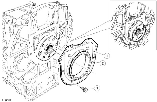
| Pos. | Spare part number | Name |
| 1 | - | Rear oil seal |
| 2 | - | Rear oil seal |
| 3 | - | Bolt (8 pcs.) |
The rear crankshaft oil seal retainer is secured to the rear of the cylinder block with 8 bolts through a rubber seal.
Crankshaft Position Sensor (CKP)
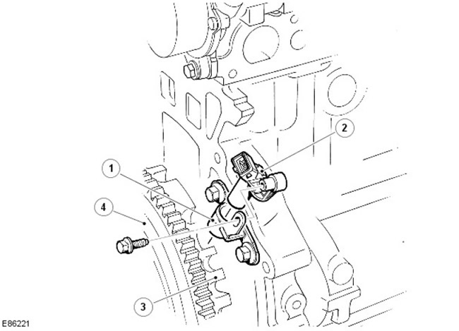
| Pos. | Spare part number | Name |
| 1 | - | CKP Mounting Bracket |
| 2 | - | CKP sensor (crankshaft rotation angle) |
| 3 | - | Impulse (setting) wheel |
| 4 | - | Flywheel |
The CKP sensor is located on the flange of the cylinder block and gearbox. The sensor generates an input signal of the crankshaft speed and position. The sensor uses the Hall effect, based on which the sensor monitors the rotation of the pulse wheel on the back of the crankshaft. If the CKP sensor bracket has been removed, it must be correctly aligned during installation.
For more information, see the chapter: Electronic controls (303-14 Electronic Controls - ID4 2.4L Diesel Engine, Description and Operating Principle).
Starter
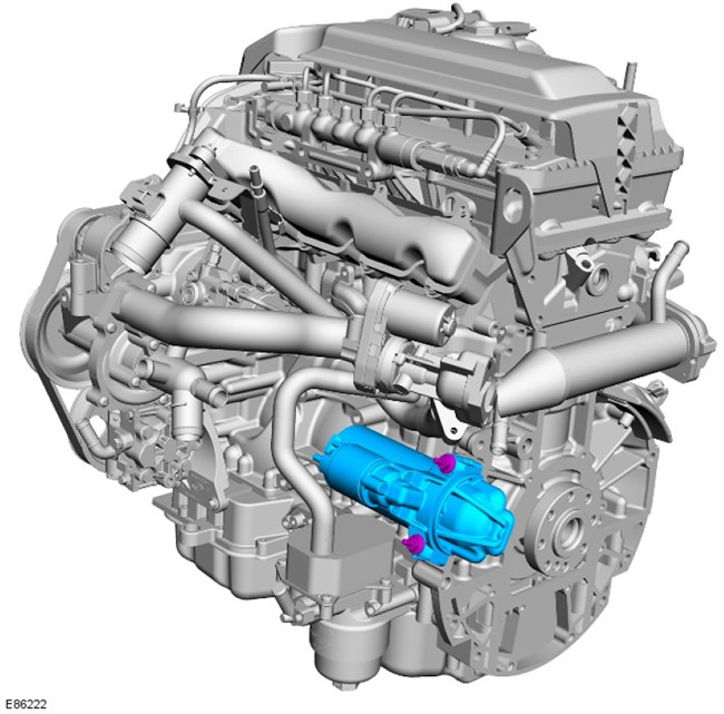
The starter is mounted at the rear left side of the cylinder block, on the gearbox flange.
For more information, see the chapter: Starting System (303-06 Starting system - Diesel engine ID4 2.4L, Description and operating principle).
Generator
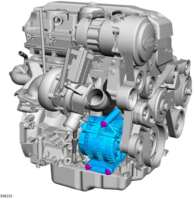
| Pos. | Spare part number | Name |
| 1 | - | Generator support bracket |
| 2 | - | Generator |
The alternator is mounted on the right side of the engine on a mounting bracket that is bolted to the cylinder block. An accessory drive belt is used to drive the alternator from the crankshaft pulley.
For more information, refer to the chapter: Generator - Diesel engine ID4 2.4L (414-02 Generator and voltage regulator - Diesel engine ID4 2.4L, Description and operating principle).
Coolant pump and vacuum pump
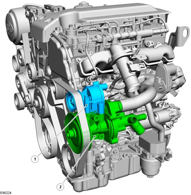
| Pos. | Spare part number | Name |
| 1 | - | Vacuum pump |
| 2 | - | Cooling system pump |
The coolant pump is mounted on the left front of the cylinder block and secured with 4 bolts. The coolant pump is driven by the crankshaft via the auxiliary drive belt. The engine thermostat is located at the rear of the coolant pump housing; the thermostat opens at 88°C.
For more information, refer to the chapter: Engine Cooling (303-03 Engine Cooling - Diesel Engine ID4 2.4L, Description and Operating Principle).
The vacuum pump is mounted on the coolant pump and secured with 3 bolts. The vacuum pump is also driven by the crankshaft via the accessory drive belt.
Power steering pump
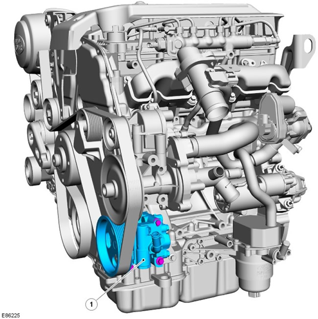
| Pos. | Spare part number | Name |
| 1 | - | Power steering pump |
The power steering pump is mounted at the front left side of the cylinder block, directly below the coolant pump. The power steering pump is secured to the mounting bracket with 3 bolts; the mounting bracket is secured to the cylinder block and ladder frame with 4 bolts.
For more information, refer to the chapter: Power Steering (211-02 Power Steering, Description and Operating Principle).
High pressure fuel pump
[Original article on the web portal: LRMAN.RU]
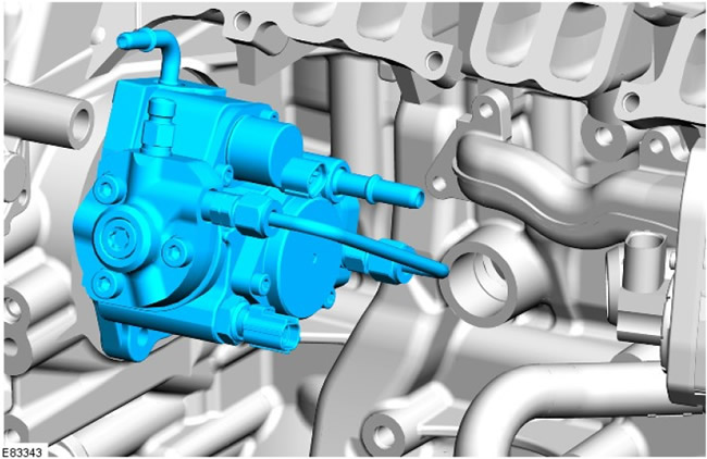
The injection pump is located under the intake manifold behind the coolant/vacuum pump assembly. The fuel pump is driven by a timing chain located at the front of the engine and consists of a low-pressure pump and a high-pressure pump that operate as a single unit.
The pump serves as a transition element between the low- and high-pressure circuits. Its purpose is to supply fuel at the required pressure under all operating conditions throughout the entire service life of the vehicle.
The transfer pump draws fuel from the fuel tank and forces it through the fuel filter. It then delivers the fuel to the high-pressure pump. The transfer pump maintains a constant fuel pressure by means of a regulating valve built into the fuel pump. This pressure is called the transfer pressure.
The high-pressure pump receives fuel under the pumping pressure from the transfer pump and increases the fuel pressure. Then the fuel under high pressure is transferred from the injection pump to the common rail fuel system.
For more information, refer to the chapter: Fuel Supply and Controls (303-04A Fuel Delivery and Controls - ID4 2.4L Diesel Engine, Description and Operation).
Coolant distribution manifold
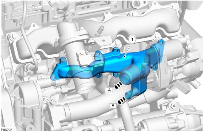
| Pos. | Spare part number | Name |
| A | - | Coolant pump connection |
| B | - | Oil cooler connection |
| 1 | - | Coolant distribution manifold |
The coolant distribution manifold is located on the left side of the cylinder block under the intake manifold. The manifold receives coolant from the coolant pump, which is then distributed to the cylinder block and to the engine oil cooler.
Comments on this article