Contents: Removal ⇩ Installation ⇩
Removal
All cars
1. Disconnect the ground wire from the battery.
For more information, refer to the chapter: Disconnecting and connecting the battery (414-01 Battery, Battery Mounting and Cables, General Procedures).
2.
WARNING: Never work on a vehicle supported only by a jack. Always support the vehicle with special stands.
Raise and support the vehicle.
3. Remove the hood.
For more information, see the chapter: Hood (501-02 Front body panels, Removal and installation).
4. Remove the cooling fan shroud.
For more information, refer to the chapter: Cooling Fan Shroud (303-03 Engine Cooling - Diesel Engine ID4 2.4L, Removal and Installation).
5. Remove the air filter.
For more information, refer to the chapter: Air Filter (303-12 Distribution and filtration of intake air - Diesel engine ID4 2.4L, Removal and installation).
6. Remove the catalytic converter.
For more information, refer to the chapter: Catalytic Converter (309-00 Exhaust system - Diesel engine ID4 2.4L, Removal and installation).
7. Remove the starter.
For more information, see chapter: Starter (303-06 Starting system - Diesel engine ID4 2.4L, Removal and installation).
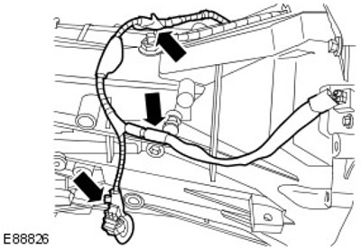
8. Disconnect the crankshaft position (CKP) sensor and the reverse light harness from the transmission. Release the 3 clamps.
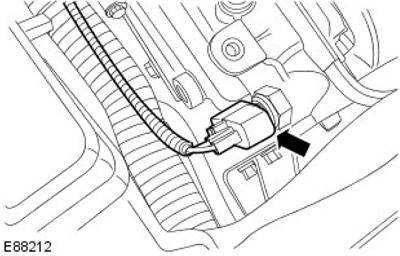
9. Disconnect the electrical connector from the reverse light switch.
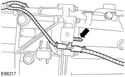
10. Disconnect the reverse light switch harness from the transmission. Release the clamp.
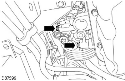
11. Completely loosen the two lower power steering pump bolts.
12. Disconnect the coolant hose from the engine oil cooler. Release the clamp.
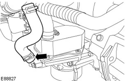
13. Disconnect the EGR heat exchanger coolant hose. Release the clamp.
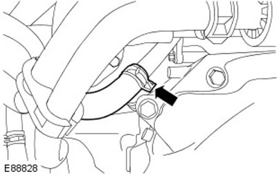
Cars with air conditioning.
14.
CAUTION: Plug all openings. Use new caps.
Disconnect the high pressure refrigerant line from the air conditioning (A/C) compressor. Remove and discard the 2 O-rings.
(Original version of the article on the website: LRMAN.ru)
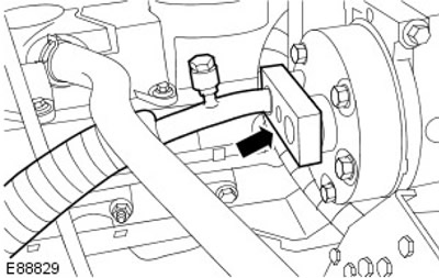
All cars
15. Remove the charge air cooler inlet pipe. Loosen the two clamps.
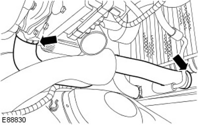
16. Disconnect the charge air cooler outlet hose. Loosen the two clamps.
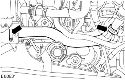
17. Disconnect the engine wiring harness electrical connector.
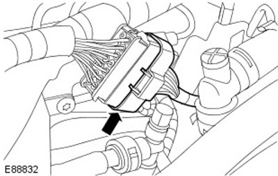
18. Disconnect the glow plug electrical connector.
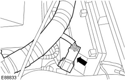
19. Release the engine wiring harness.
- Disconnect the 3 electrical connectors from the Engine Control Module (ECM).
- Release the 2 clamps.
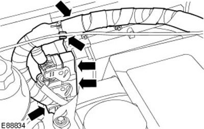
20. Disconnect the wiring harness from the coolant hose on the heater.
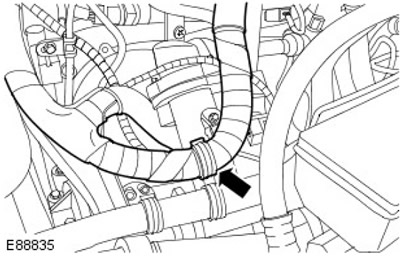
21. Disconnect the upper radiator coolant hose. Release the clamp.
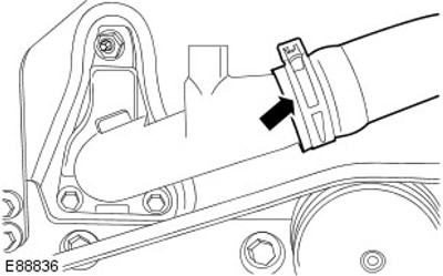
22. Disconnect the 3 coolant hoses from the pump housing. Release the 3 clamps.
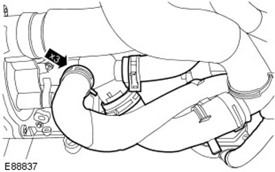
23. Disconnect the brake booster vacuum line from the brake system vacuum pump.
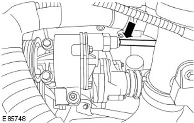
24. Remove the accessory drive belt from the power steering pump pulley. Loosen the belt tension.
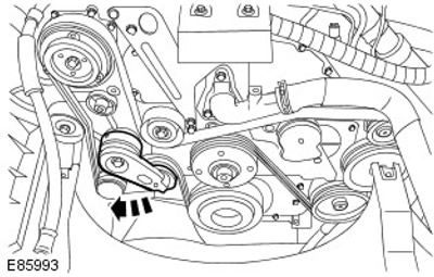
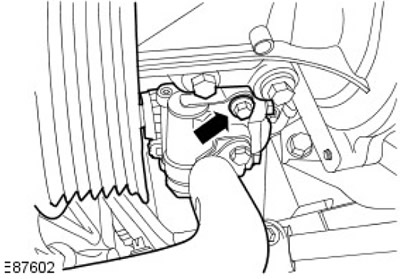
25. Remove the power steering pump.
- Remove the remaining bolt.
- Tie the power steering pump separately from other components.
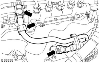
26.
CAUTION: Plug all openings. Use new caps.
Disconnect 2 fuel lines. Release the return fuel line from the clamp.
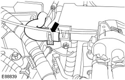
27. Disconnect the heater coolant hose from the heater control valve. Release the clamp.
28. Disconnect the EGR heat exchanger coolant hose.
- Release the clamp.
- Disconnect the coolant hoses from the EGR heat exchanger.
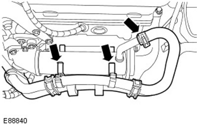
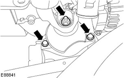
29. Release the right engine support.
- Remove the nut.
- Remove two bolts.
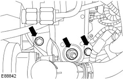
30. Release the left engine mount.
- Remove the nut.
- Remove two bolts.
31. Raise and support the vehicle. Use a hydraulic jack to support the gearbox.
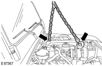
32. Remove both engine mounts.
33. Remove the 5 left bolts connecting the engine to the gearbox.
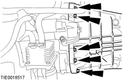
34. Remove the 5 right bolts connecting the engine to the gearbox.
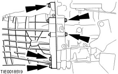
35. With the help of a second mechanic, carefully remove the engine.
Installation
All cars
1. With the help of a second mechanic, carefully install the engine. Clean the contact surfaces of the parts.
2. Attach the engine to the gearbox.
- Tighten the bolts (tightening torque 40 Nm).
- Remove the hydraulic jack from under the transmission.
3. Install the left engine mount.
4. Install the right engine mount.
5. Secure both engine mounts.
- Lower the engine onto its mounts.
- Tighten the bolts (tightening torque 80 Nm).
- Tighten the nuts (tightening torque 80 Nm).
6. Connect the exhaust gas recirculation (EGR) heat exchanger coolant hose.
- Secure the clamp.
- Attach the coolant hoses to the EGR heat exchanger.
7. Connect the heater coolant hose to the heater control valve. Secure the clamp.
8.
NOTE: Remove and discard plugs.
Connect the fuel lines.
- Secure the clamp.
- Secure the fuel return line to the clamp.
9. Secure the power steering pump.
- Remove and discard the clamp.
- Tighten the bolts to 23 Nm.
10. Secure the accessory drive belt to the power steering pump pulley.
11. Connect the brake booster vacuum line to the brake system vacuum pump.
12. Connect the coolant hoses to the coolant pump housing. Secure the clamps.
13. Connect the upper radiator coolant hose. Secure the clamp.
14. Secure the engine wiring harness.
- Connect the engine control module (ECM) electrical connectors.
- Secure the clamps.
15. Connect the glow plug electrical connector.
16. Connect the engine wiring harness electrical connector.
17. Install the charge air cooler outlet hose. Tighten the clamps.
18. Install the charge air cooler intake duct. Tighten the clamps.
Cars with air conditioning
19.
NOTE: Remove and discard plugs.
Connect the high pressure line of the air conditioning compressor.
- Install new O-rings.
All cars
20. Reinstall the air filter.
For more information, refer to the chapter: Air Filter (303-12 Distribution and filtration of intake air - Diesel engine ID4 2.4L, Removal and installation).
21. Connect the coolant hose to the EGR heat exchanger. Secure the clamp.
22. Connect the coolant hose to the engine oil cooler. Secure the clamp.
23. Connect the electrical connector of the reverse light switch.
24. Attach the Crankshaft Position (CKP) Sensor and Reverse Light Switch Wiring Harness to the Transmission. Secure with cable ties.
25. Install the starter.
For more information, see chapter: Starter (303-06 Starting system - Diesel engine ID4 2.4L, Removal and installation).
26. Install the catalytic converter.
For more information, refer to the chapter: Catalytic Converter (309-00 Exhaust system - Diesel engine ID4 2.4L, Removal and installation).
27. Install the cooling fan shroud.
For more information, refer to the chapter: Cooling Fan Shroud (303-03 Engine Cooling - Diesel Engine ID4 2.4L, Removal and Installation).
28. Connect the ground wire to the battery.
For more information, refer to the chapter: Connecting the Battery (414-01 Battery, Battery Mounting and Cables, General Procedures).
29. Install the hood.
For more information, see the chapter: Hood (501-02 Front body panels, Removal and installation).
Comments on this article