Special tool(s)
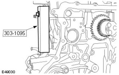
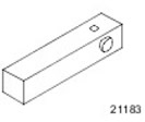 | Ladder Frame Adjustment Tool 303-1095 |
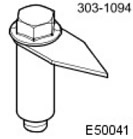 | Pointer, top dead center (TDC) 303-1094 |
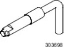 | Crankshaft Alignment Tool 303-698 |
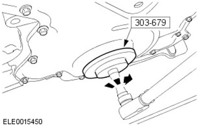
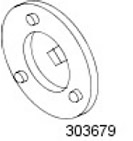 | Front Crankshaft Oil Seal Remover/Installer 303-679 |
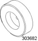 | Adjustment Tool, Front Engine Cover 303-682 |
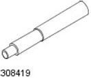 | Clutch Adjustment Tool 308-419 |
Assembly
1.
NOTE: The grooves in the crankshaft thrust rings must face up.
Install the crankshaft thrust washers. Lubricate the thrust washers with clean engine oil.
2. Install the crankshaft.
- Lubricate the crankshaft journals and crankshaft main bearing shells with clean engine oil.
- Install the crankshaft main bearing shells.
3.
Warnings:
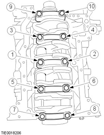
- Assemble the caps so that the arrows point forward. The caps are labeled, starting from the front, in the following order: F, 2, 3, 4, R.
- Crankshaft main bearing cap bolts may only be used 4 times.
- Tighten the bolts in three stages in the sequence shown.
NOTE: Lubricate the crankshaft and crankshaft main bearing shells with clean engine oil.
NOTE: Use a center punch to mark the bolt heads for reuse.
Install the crankshaft main bearing caps.
- Stage 1: 45 Nm.
- Stage 2: 80 Nm.
- Stage 3: 105 degrees.
4.
CAUTION: Be careful not to damage the connecting rod big end bearing surface of the crankshaft connecting rod.
NOTE: The piston ring gaps must be evenly distributed around the piston circumference. This also applies to the oil scraper ring elements. Position the piston ring gaps at an angle of 120 degrees to each other.
NOTE: The arrow on the piston must point towards the front of the engine.
Using the appropriate tool, install the pistons. Lubricate the pistons and cylinder bores with clean engine oil.
5.
Warnings:
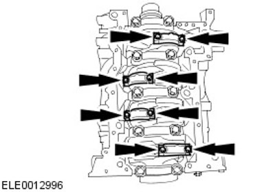
- Connecting rod bearing cap bolts may only be used 4 times.
- Check that the connecting rod bearing cap with a profiled connector is installed correctly.
NOTE: Use a center punch to mark the bolt heads for reuse.
NOTE: The identification marks on the big end bearing caps must face toward the front of the engine.
Install the connecting rod bearing shells.
- Lubricate the connecting rod bearing shells with clean engine oil.
- Tighten the bolts in two steps.
- Stage 1: 30 Nm.
- Stage 2: 80 degrees.
6.
CAUTION: Do not cut or damage protruding foam pads.
NOTE: Install new step frame spacers.
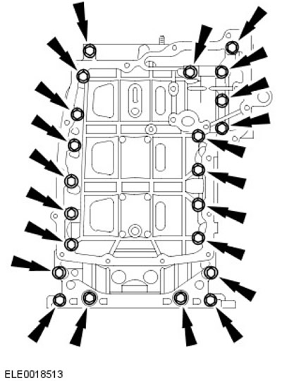
Install the step frame. Screw in the bolts, but do not tighten them.
7.
CAUTION: The step frame and cylinder block must be aligned so that the side clearance does not exceed 0.05 mm either way.
Using a special tool, align the step frame position relative to the cylinder block.
8.
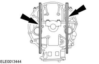
CAUTION: The position of the step frame and cylinder block must be adjusted so that the misalignment at the rear does not exceed 0.01 mm overlap / 0.2 mm clearance.
Using a suitable straight edge, align the step frame with the cylinder block.
9.
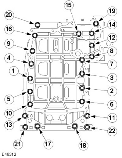
NOTE: Tighten the bolts in the order shown in the illustration.
Secure the step frame. Tighten the bolts to 23 Nm.
10.
NOTE: Install a new crankshaft rear oil seal.
NOTE: The new crankshaft rear oil seal is equipped with a locating sleeve that must be removed after installation.
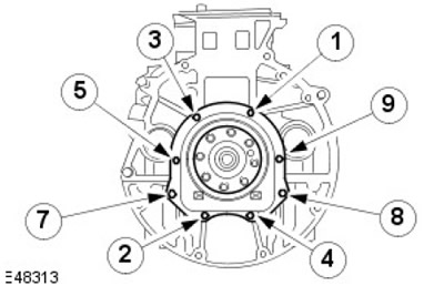
NOTE: Tighten the bolts in the order shown in the illustration.
Install the rear crankshaft oil seal. Tighten the bolts (tightening torque 10 Nm).
11. Remove the special tools. Unscrew the bolt.
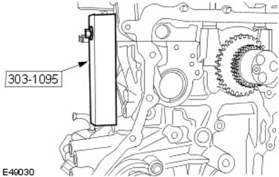
12.
NOTE: Do not fully tighten the fuel pump bolts at this stage.
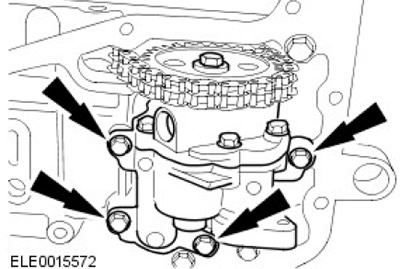
Install the oil pump and oil pump chain. Place the oil pump chain on the crankshaft sprocket.
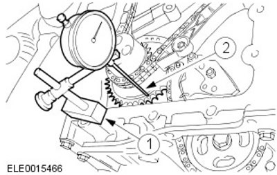
13. Using a suitable dial indicator, take a check measurement at the front of the crankshaft sprocket.
- 1. Place the dial indicator stand on the cylinder block.
- 2. Place the dial indicator plunger against the crankshaft sprocket and set the indicator to zero.
14.
NOTE: Take measurements at two different points on the oil pump sprocket.
Using a dial indicator, align the oil pump sprocket and tighten the oil pump mounting bolts.
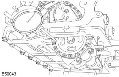
15. Check the alignment of the oil pump sprocket to the crankshaft sprocket. Repeat the alignment procedure if necessary.
16. Secure the oil pump. Tighten the bolts (tightening torque 10 Nm).
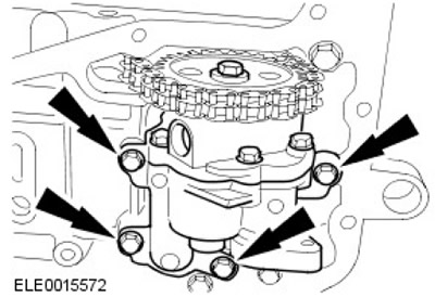
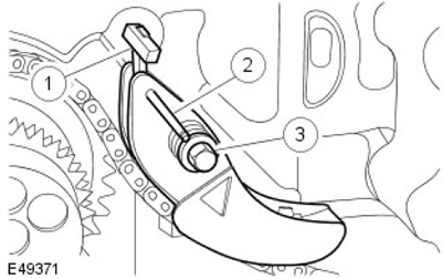
17. Install the oil pump chain tensioner.
- 1. Install the spring onto the stud.
- 2. Unlock the tensioner by removing the pin.
- 3. Tighten the bolt (tightening torque 22 Nm).
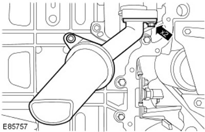
18.
NOTE: Install the O-ring.
Install the oil pump pickup tube. Tighten the bolts (tightening torque 10 Nm).
19.
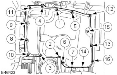
NOTE: Tighten the bolts in two steps in the sequence shown.
Install a new oil pan.
- Apply a 3mm wide bead of recommended sealant to the oil pan.
- Step 1: Tighten bolts 1 through 16 to 7 Nm.
- Step 2: Tighten bolts 1 through 16 to 14 Nm.
20.
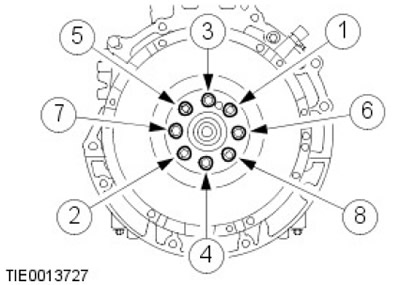
NOTE: Install new flywheel bolts.
NOTE: Tighten the bolts in three stages, working in the sequence shown.
Install the flywheel.
- Stage 1: 25 Nm.
- Stage 2: 40 Nm.
- Stage 3: 48 degrees.
21.
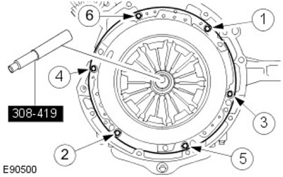
NOTE: Tighten the bolts in the order shown in the illustration.
Using the special tool, install the clutch slave and pressure plates. Tighten the bolts (tightening torque 29 Nm).
22.
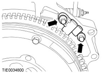
NOTE: Do not fully tighten the crankshaft position sensor bracket bolts at this stage.
Install the crankshaft position (CKP) sensor bracket.
23.
NOTE: Do not move the special tool after installation.
Install the special tool.
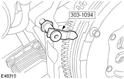
24. Turn the crankshaft so that piston No.1 is located approximately 10 mm before top dead center (TDC).
25. Install the digital indicator on the cylinder block.
- Install the digital indicator plunger onto piston No.1.
- Set the dial indicator to zero.
26. Mark the position on the flywheel.
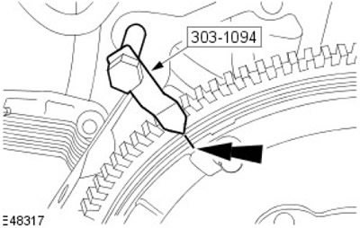
27.
NOTE: Turn the crankshaft counterclockwise.
Turn the crankshaft until piston No.1 is at the zero position on the dial indicator. Mark the position on the flywheel.
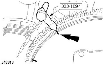
28. Repeat the previous steps to ensure that the marks are applied correctly.
29.
NOTE: The middle position between the marks is top dead center (TDC).
Measure the distance between the two marks.
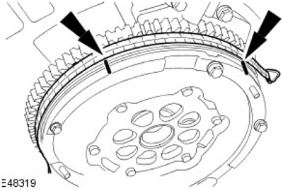
30. Divide the value by two and mark the TDC position on the primary section of the flywheel.
31. Measure the flywheel circumference.
32.
NOTE: Mark the calculated value on the primary section of the flywheel, measured counterclockwise from TDC.
Multiply the circumference by 0.1388.
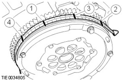
- 1. First mark.
- 2. Second mark.
- 3. Calculated position of TDC.
- 4. The calculated position is 50 degrees before TDC.
33.
NOTE: Turn the crankshaft in the normal direction of rotation to the calculated position mark 50 degrees before TDC.
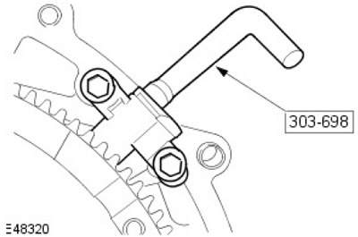
Install the special tool.
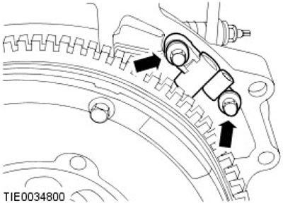
34. Secure the crankshaft position (CKP) sensor bracket. Tighten the bolts to 23 Nm.
35.
NOTE: Clean the mating surface of the element.
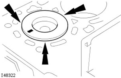
NOTE: Measure the piston extension of each cylinder at TDC.
NOTE: The cylinder head gasket is selected based on the highest measurement result.
Measure the distance between the piston crown and the cylinder block at the indicated points.
- Use the chart to determine the correct cylinder head gasket thickness.
For more information, please refer to the chapter: Specifications (303-01 Engine - Diesel Engine ID4 2.4L, Specifications).
36.
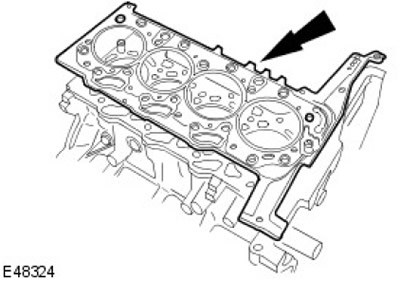
CAUTION: The thickness of the new cylinder head gasket depends on the piston protrusion (marked hole/tooth).
Install a new cylinder head gasket.
37.
CAUTION: Install new cylinder head bolts.
NOTE: Clean the mating surface of the element.
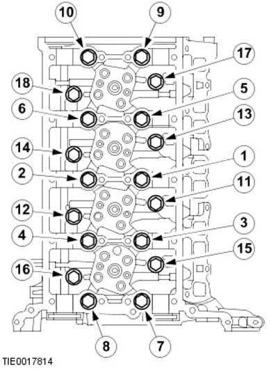
Install the cylinder head.
- Tighten the bolts in six steps in the sequence shown.
- Stage 1: Tighten bolts 1 through 10 to 20 Nm.
- Step 2: Tighten bolts 11 through 18 to 10 Nm.
- Step 3: Tighten bolts 1 through 10 to 40 Nm.
- Step 4: Tighten bolts 11 through 18 to 20 Nm.
- Step 5: Tighten bolts 1-10 180 degrees.
- Step 6: Tighten bolts 11 - 18 180 degrees.
- Step 7: Tighten the M6 bolt to 10 Nm.
38.
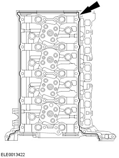
NOTE: Clean the mating surface of the element.
Apply a 2.5mm bead of recommended sealant to the cylinder head.
39.
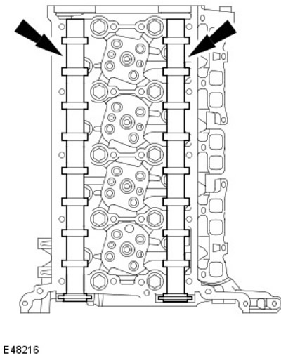
NOTE: Clean the contact surfaces of the parts.
Install the camshafts. Lubricate the camshaft journals and cams with clean engine oil.
40.
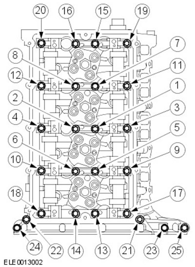
NOTE: Tighten the bolts in two steps in the sequence shown.
Install the camshaft housing.
- Step 1: Tighten bolts 1 through 22 to 23 Nm.
- Step 2: Tighten bolts 23 to 25 to 10 Nm.
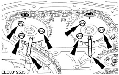
41. Using a suitable 6 mm diameter rod, lock the camshaft sprockets. Tighten the camshaft sprocket bolts.
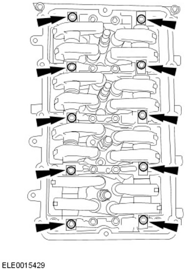
42.
Warnings:
- New bolts should be installed.
- Tighten the bolts in the order shown in the illustration.
NOTE: Lubricate the rocker arm shafts with clean engine oil.
NOTE: The oil supply holes in the rocker arm shafts must face down.
Install the rocker shafts.
- Step 1: Tighten the bolts (tightening torque 13 Nm).
- Stage 2: 45 degrees.
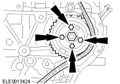
43. Install the high pressure fuel pump. Tighten the bolts (tightening torque 22 Nm).

44.
NOTE: Do not tighten the bolts at this stage.
Install the high pressure fuel pump sprocket. Install the bolts but do not tighten them.
45.
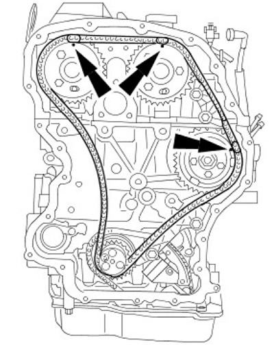
CAUTION: Make sure the painted links are aligned with the timing marks. Failure to do so may result in damage to the vehicle.
Install the timing chain.
46.
CAUTION: Make sure the timing chain tensioner is fully retracted before installation. Failure to do so may result in vehicle damage.
Install the timing chain guides and tensioner.
- Tighten the bolts (tightening torque 15 Nm).
- Tighten the nut (tightening torque 15 Nm).
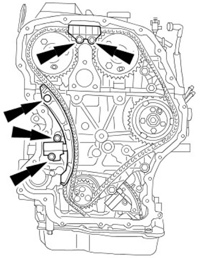
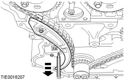
47. Unlock the timing chain tensioner. Remove the stud.
48. Tighten the intake camshaft sprocket mounting bolt to 35 Nm.
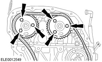
49. Tighten the fuel injection pump sprocket bolts to 33 Nm.
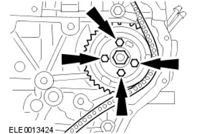
50. Remove the 6mm rods.
51. Remove the special tools.
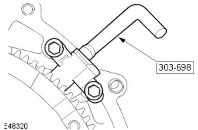
52. Turn the crankshaft clockwise 2 full turns.
53.
CAUTION: Make sure the special tool is properly installed on the flywheel.
Check the valve timing by inserting a special tool into the CKP sensor hole.
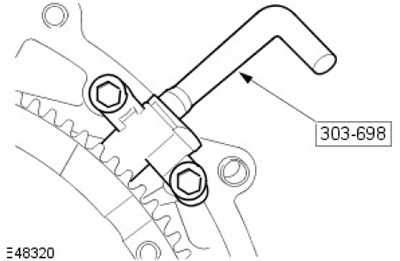
54. Check the camshaft timing by inserting a suitable 6mm diameter rod into the holes in the camshaft sprockets.
55. Remove the special tools.
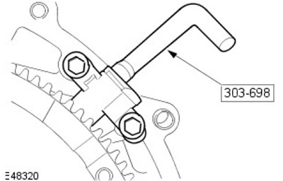
56. Remove the 6mm rods.
57.
NOTE: Clean the contact surfaces of the parts.
Using the special tool, install the new timing chain cover.
- Apply a 3mm bead of recommended sealant to the timing chain cover.
- Tighten the bolts (tightening torque 14 Nm).
- Tighten the nuts (tightening torque 10 Nm).
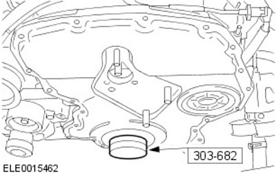
58. Remove the special tools.
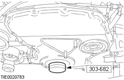
59.
NOTE: Install a new front crankshaft oil seal.
NOTE: The new front crankshaft oil seal is supplied with a locating sleeve that must be removed during installation.
Using the special tool, install the front crankshaft oil seal.
60.
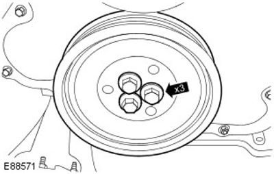
Warnings:
- Tighten the bolts in the order shown in the illustration.
- New bolts should be installed.
Install the crankshaft pulley.
- Stage 1: 45 Nm.
- Stage 2: 120 degrees.
61.
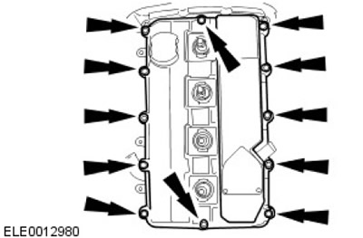
NOTE: Install a new cylinder head cover gasket.
Install the cylinder head cover. Tighten the bolts (tightening torque 10 Nm).
62. Install the CKP sensor. Tighten the bolt (tightening torque 7 Nm).
63.
NOTE: Clean the contact surfaces of the parts.
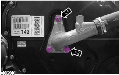
Install the coolant outlet elbow pipe onto the cylinder head.
- Install the sealing ring.
- Tighten the nut (tightening torque 22 Nm).
- Tighten the bolts (tightening torque 22 Nm).
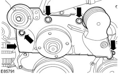
64. Install the accessory drive component bracket.
- Tighten the M10 bolts to 48 Nm.
- Tighten the M8 bolts (tightening torque 22 Nm).
65.
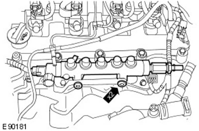
CAUTION: At this stage, tighten the bolts only finger tight.
Install the fuel manifold.
- Install the bracket.
- Screw in the bolts, but do not tighten them.
66. Install the injectors. Install new sealing washers.
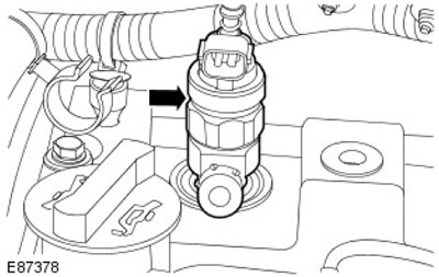
67.
Warnings:
- The injector clamp bolts can only be used twice.
- Tighten the bolts in the order shown in the illustration.
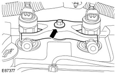
Secure the injectors.
- Install the injector clamps.
- Step 1: Tighten the bolts (tightening torque 6 Nm).
- Stage 2: 180 degrees.
- Install the injector clamp covers.
68.
CAUTION: Remove and discard plugs.
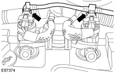
Connect the injector return fuel line. Install the clamps.
69.
Warnings:
- Apply pressure to the high pressure fuel supply line to keep the sealing lenses in contact with the fuel injector cones and fuel rail when connecting.
- Avoid striking the sealing lenses of the high-pressure fuel supply line, as this may damage the ends of the line and allow dirt to enter the fuel injection system.
- At this stage, tighten the connections with hand force only.
NOTE: Remove and discard plugs.
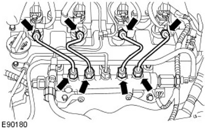
Install new high pressure fuel supply lines.
70.
Warnings:
- Tighten the high pressure fuel supply lines in the order shown in the illustration.
- Remove and discard the plugs.
Secure the high pressure fuel lines.
- Step 1: Tighten the high pressure fuel supply line unions on the fuel injectors and fuel pump to 35 Nm.
- Step 2: Tighten the high pressure fuel supply line clamps to 10 Nm.
- Step 3: Tighten the fuel rail bolts to 23 Nm.
- Step 4: Tighten the high pressure fuel supply line unions on the fuel rail side to 35 Nm.
71. Install the engine wiring harness.
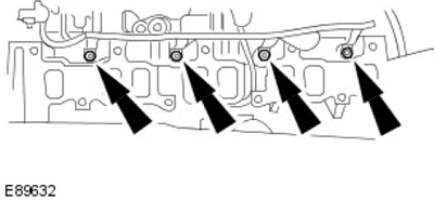
72. Connect the glow plug wiring harness. Tighten the nuts (tightening torque 2 Nm).
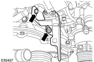
73. Secure the engine wiring harness support bracket.
- Tighten the nut (tightening torque 10 Nm).
- Tighten the bolt to 10 Nm.
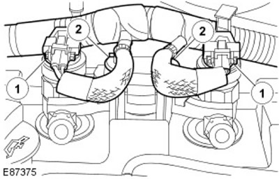
74. Connect the electrical connectors of the injectors.
- Secure the injector wiring harness.
- Secure with clamps.
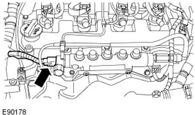
75. Connect the fuel rail pressure (FRP) sensor electrical connector.
76.
NOTE: Make sure the engine wiring harness is properly positioned.
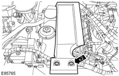
Replace the engine cover. Tighten the bolts (tightening torque 10 Nm).
77.
CAUTION: Remove and discard plugs.
[Information obtained from the website: LRman.ru]
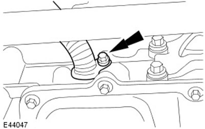
Install the turbocharger oil return line.
- Install the sealing ring.
- Install the clamp.
- Tighten the bolt (tightening torque 22 Nm).
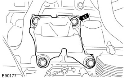
78. Install the right engine mount bracket. Tighten the bolts (tightening torque 63 Nm).
79.
CAUTION: New nuts must be used.
NOTE: Clean the contact surfaces of the parts.
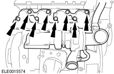
Install the turbocharger assembly with the exhaust manifold.
- Install a new gasket.
- Tighten the nuts (tightening torque 40 Nm).
- Tighten the bolts (tightening torque 40 Nm).
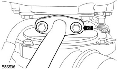
80. Secure the turbocharger return oil line.
- Install a new gasket.
- Tighten the bolts (tightening torque 10 Nm).
81.
CAUTION: Remove and discard plugs.
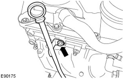
Insert the oil level dipstick and install the oil level dipstick tube.
- Install the sealing ring.
- Tighten the bolt (tightening torque 10 Nm).
- Secure the wiring harness.
82.
CAUTION: Remove and discard plugs.
NOTE: Clean the contact surfaces of the parts.
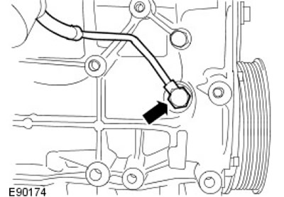
Connect the turbocharger oil supply line.
- Install new sealing washers.
- Tighten the hollow bolt to 35 Nm.
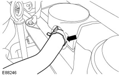
83. Connect the breather pipe. Secure the clamp.
84. Connect the turbocharger actuator electrical connector.
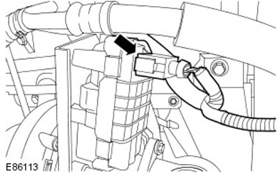
85. Secure the MAF sensor wiring harness. Secure with a clamp.
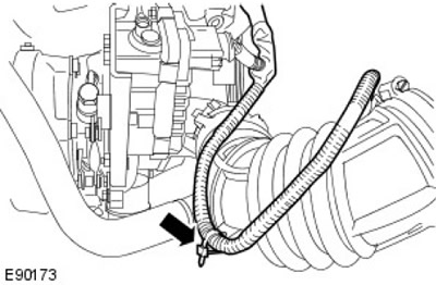
86. Install the generator support bracket. Tighten the bolts (tightening torque 25 Nm).
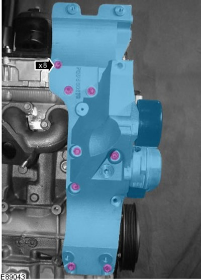
87. Install the turbocharger heat shield bracket.
- Tighten the M6 bolt to 10 Nm.
- Tighten the M8 bolts (tightening torque 20 Nm).
88. Connect the generator. Tighten the bolts (tightening torque 48 Nm).
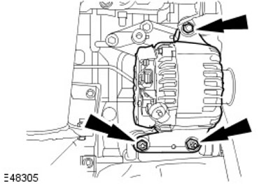
89. Connect the generator electrical connector.
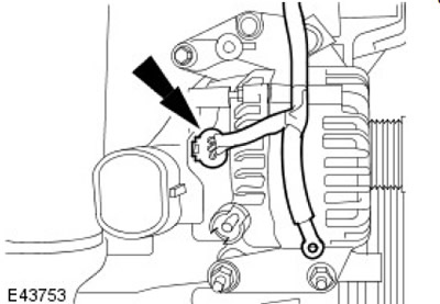
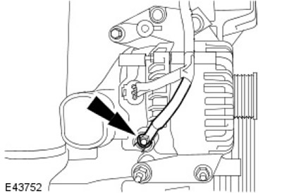
90. Connect the positive battery cable to the alternator. Tighten the nut (tightening torque 8 Nm).
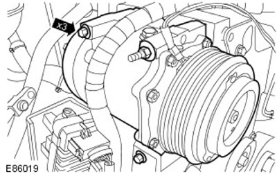
91. Install the air conditioning compressor. Tighten the bolts (tightening torque 22 Nm).
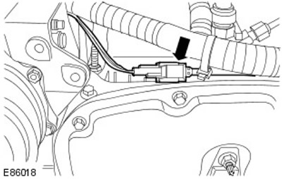
92. Connect the air conditioning compressor electrical connector.
93. Install the engine lift bracket. Tighten the bolts to 10 Nm.
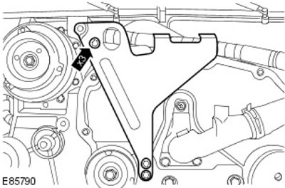
94. Install the air conditioning compressor pulley cover.
- Install the accessory drive belt onto the air conditioning compressor pulley.
- Tighten the bolts to 10 Nm.
- Tighten the nut (tightening torque 10 Nm).
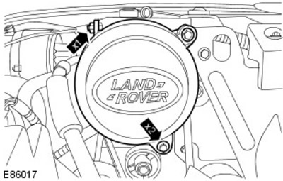
95.
CAUTION: Remove and discard plugs.
NOTE: Clean the contact surfaces of the parts.
Install the oil filter housing assembly.
- Install a new gasket.
- Tighten the bolts to 23 Nm.
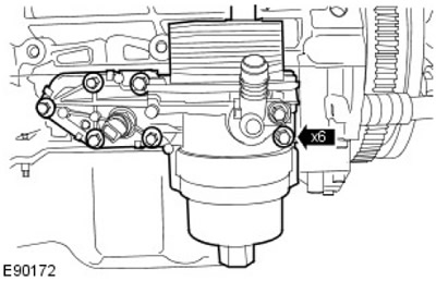
96. Install the left engine mount bracket. Tighten the bolts (tightening torque 63 Nm).
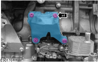
97. Install the power steering pump bracket. Tighten the bolts to 23 Nm.
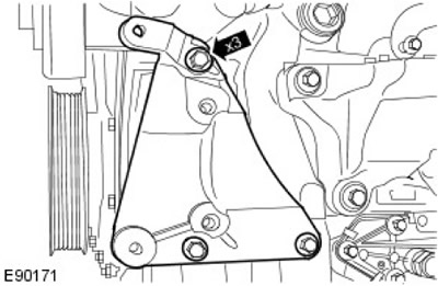
98. Install the coolant pump and coolant manifold assembly.
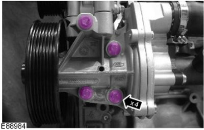
99.
NOTE: Clean the contact surfaces of the parts.
Secure the coolant pump.
- Install a new gasket.
- Tighten the bolts to 23 Nm.
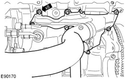
100. Secure the coolant manifold.
- Install a new gasket.
- Tighten the bolts to 10 Nm.
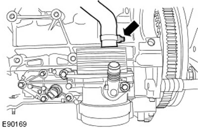
101. Connect the coolant hose. Secure the clamp.
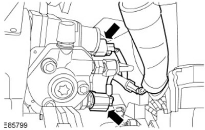
102. Connect the electrical connectors of the fuel metering valve and fuel temperature sensor.
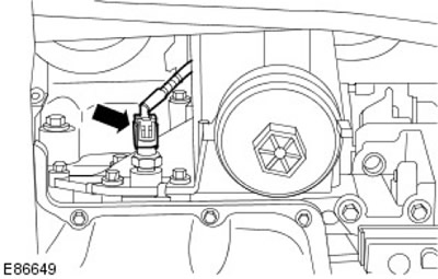
103. Connect the electrical connector of the engine oil pressure (EOP) sensor.
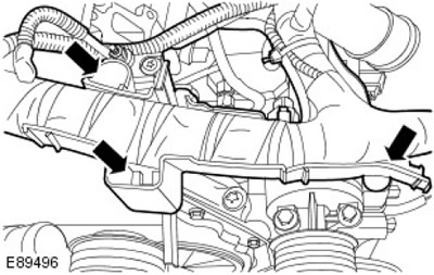
104. Secure the engine wiring harness. Secure with three clamps.
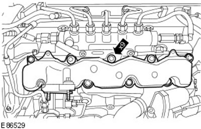
105.
NOTE: Clean the contact surfaces of the parts.
Install the EGR valve outlet pipe and intake manifold assembly.
- Install new intake manifold seals.
- Tighten the bolts (tightening torque 15 Nm).
106. Secure the EGR valve outlet pipe. Tighten the bolt to 23 Nm.
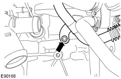
107.
CAUTION: Remove and discard plugs.
Install the high pressure fuel pump fuel supply line. Tighten the bolt (tightening torque 7 Nm).
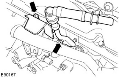
108. Secure the engine wiring harness.
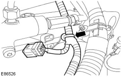
109. Connect the camshaft position (CMP) sensor electrical connector.
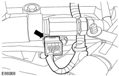
110.
NOTE: Clean the contact surfaces of the parts.
Install the EGR valve and EGR cooler.
- Install new gaskets.
- Tighten the M8 bolts (tightening torque 23 Nm).
- Tighten the M6 bolts (tightening torque 10 Nm).
- Connect the EGR valve electrical connector.
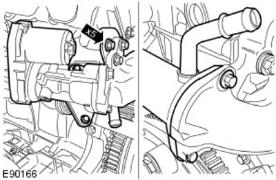
111. Connect the CKP sensor electrical connector.
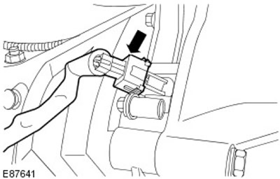
112. Remove the engine from the stand.
Comments on this article