Contents: Drive gear ⇩ Front cover ⇩
The main elements of the camshaft system are:
- Drive gear assembly
- Front cover
Drive gear
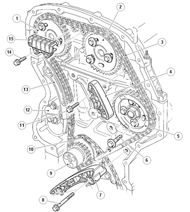
| Pos. | Spare part number | Name |
| 1 | - | Exhaust shaft sprocket |
| 2 | - | Intake shaft sprocket |
| 3 | - | Main drive chain |
| 4 | - | Main drive chain guide |
| 5 | - | Fuel injection pump sprocket |
| 6 | - | Bolt (4 pcs.) |
| 7 | - | Main drive chain guide |
| 8 | - | Bolt (2 pcs.) |
| 9 | - | Crankshaft sprocket |
| 10 | - | Additional drive chain |
| 11 | - | Bolt (2 pcs.) |
| 12 | - | Automatic tensioner |
| 13 | - | Main drive chain tensioner lever |
| 14 | - | Bolt (4 pcs.) |
| 15 | - | Main drive chain guide |
The multi-link main drive chain transmits rotation from the crankshaft sprocket to the exhaust camshaft, intake camshaft and high-pressure fuel pump. The additional drive chain transmits rotation from the crankshaft sprocket to the oil pump located at the bottom of the ladder frame.
The drive sprocket is secured to the crankshaft with one bolt, 3 bolts secure the torsional vibration damper to the crankshaft through holes in the drive sprocket. The position of the intake and exhaust camshaft sprockets is adjusted using a bushing tool and an adjusting pin. Once set in the correct position, 3 bolts are used to secure the sprockets to the camshafts.
Each chain has a hydraulic tensioner that operates on engine oil. The main chain is lubricated through syringe tubes located in the center of the front of the cylinder block. The additional chain is lubricated by spraying oil from the ladder frame and from the oil pan. The primary chain tensioner acts on the pivoting flexible tensioner plates. The secondary chain tensioner acts directly on the chain. The guides are mounted on the drive side of the primary chains.
Front cover
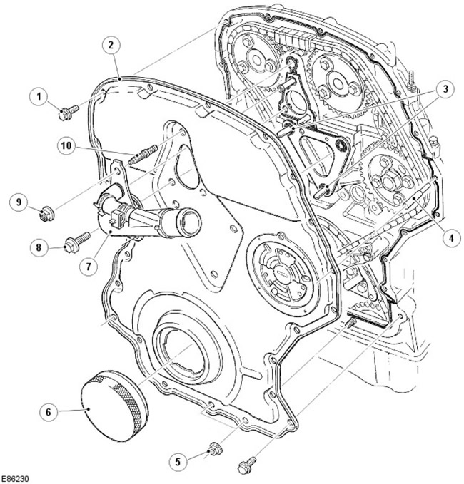
| Pos. | Spare part number | Name |
| 1 | - | Bolt (20 pcs.) |
| 2 | - | Front cover |
| 3 | - | Pin |
| 4 | - | Guide pin |
| 5 | - | Nut (2 pcs.) |
| 6 | - | Centering tool |
| 7 | - | Water outlet device |
| 8 | - | Bolt (2 pcs.) |
| 9 | - | Screw |
| 10 | - | Hairpin |
The stamped steel front cover is secured with 20 bolts to the front of the cylinder block, cylinder head and ladder frame, and is sealed with a small amount of room temperature vulcanizing (RTV) silicone sealant.
Installing the front cover requires a special tool that is inserted into the camshaft sprocket hole to center the cover.
Comments on this article