Contents: Oil return using turbocharger ⇩ Oil receiver ⇩ Oil pump ⇩ Oil filter and oil cooler assembly ⇩ Operation of the lubrication system ⇩
The main components of the lubrication system are:
- Turbocharger return oil line
- Oil pickup tube
- Oil pump
- Oil filter and oil cooler assembly
- Oil pressure sensor
- Oil dipstick
Oil return using turbocharger
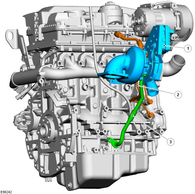
| Pos. | Spare part number | Name |
| 1 | - | Turbocharger assembly |
| 2 | - | Turbocharger oil feed line |
| 3 | - | Turbocharger return oil line |
The turbocharger oil feed pipe is connected to a conical bore on the right front of the cylinder block, behind the alternator mounting bracket, via a banjo connection. The turbocharger bearings are thus lubricated through the conical bore by high pressure oil created by the oil pump.
On the left side of the ladder frame, under the turbocharger, there is an opening for the pipe that carries oil back from the turbocharger to the oil pan.
Oil receiver
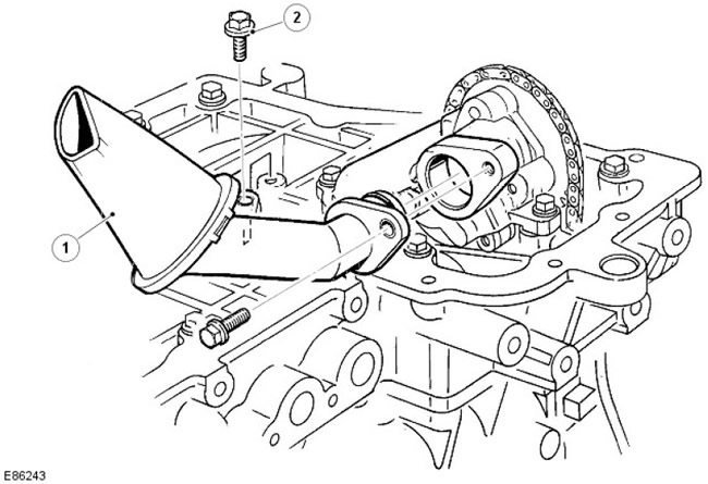
| Pos. | Spare part number | Name |
| 1 | - | Oil pickup tube |
| 2 | - | Bolt (2 pcs.) |
The welded steel oil pick-up tube is immersed in a corresponding recess in the oil pan and ensures the supply of oil in all normal operating conditions. A sieve on the inlet prevents foreign particles from entering the lubrication system.
Oil pump
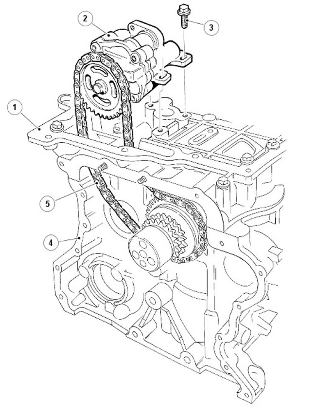
| Pos. | Spare part number | Name |
| 1 | - | Staircase construction |
| 2 | - | Bolt (4 pcs.) |
| 3 | - | Oil pump |
| 4 | - | Cylinder block |
| 5 | - | Oil pump drive chain |
The oil pump is located in the left front part (bottom) of the ladder frame and is secured with 4 bolts. It is driven by a chain through the crankshaft sprocket. Oil is supplied to the pump from the main gallery through holes in the cylinder block.
The chain is tensioned and guided by means of a hydraulic chain tensioner.
Oil filter and oil cooler assembly
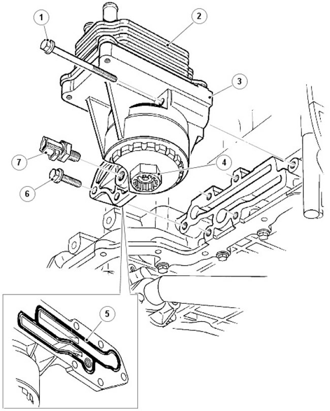
| Pos. | Spare part number | Name |
| 1 | - | Bolt (2 pcs.) |
| 2 | - | Oil radiator |
| 3 | - | Oil filter housing |
| 4 | - | Oil filter drain plug |
| 5 | - | Oil filter and oil cooler assembly seal |
| 6 | - | Bolt (4 pcs.) |
| 7 | - | Oil pressure sensor |
The engine is lubricated through a pressure lubrication system using an oil filter assembly and an oil cooler.
The oil filter and oil cooler assembly is mounted on the left side of the ladder frame and includes a full-flow, replaceable canister-type filter, an oil cooler, and an oil pressure sensor. The support plate is centered relative to the oil gallery in the ladder frame and is sealed with an O-ring.
The engine cooling system cools the oil in the radiator. Its operation is regulated by a separate thermostat, which prevents coolant from entering through the oil radiator at low engine temperatures, ensuring rapid engine warm-up. The thermostat opens at 75±2°C.
Oil is supplied to and discharged from the oil cooler through galleries in the cylinder block. Hoses from the engine cooling system, providing supply and return of coolant, are connected to two pipes of the oil radiator.
Operation of the lubrication system
From the oil pan, through the mesh filter and oil inlet pipe, the oil enters the oil pump, which has a built-in oil relief valve. The mesh filter and oil inlet pipe prevent foreign particles from passing through the oil pump, thereby protecting it from damage and preventing clogging of the oil channels. The oil relief valve in the oil pump opens when the oil pressure becomes too high and diverts the oil back around the pump.
The lubrication system is designed in such a way that most of the oil flow is directed to the main oil gallery of the cylinder block, and a smaller part (determined by the limiter in the oil filter housing) - into the oil cooler. The remaining oil flow from the outside of the oil filter is combined with the return flow from the oil cooler and then fed into the main oil gallery of the cylinder block.
The main oil gallery has passages through which oil is supplied to the cylinder head and main bearings. Cross-drilled holes in the crankshaft main bearings supply oil to the connecting rod lower head bearings. Oil galleries in the cylinder head supply oil to the camshafts and hydraulic lash adjusters.
The oil pressure sensor is located in the oil filter and on the oil cooler support plate; it measures the oil pressure level in front of the main gallery of the cylinder block. When low oil pressure is detected, a warning lamp on the instrument panel comes on.
Oil under low pressure enters the cylinder head through the dowel pin stop in the cylinder block/cylinder head. The oil then flows through a channel in the cylinder head bore into the camshaft housing and is supplied through separate holes to the camshaft bearings and hydraulic tappet housings. Return oil from the cylinder head flows into the oil pan through the cylinder head bolt channels.
Comments on this article