- Crankshaft and main bearings
- Ladder frame and sump
- Oil filter and oil cooler assembly
Crankshaft and main bearings
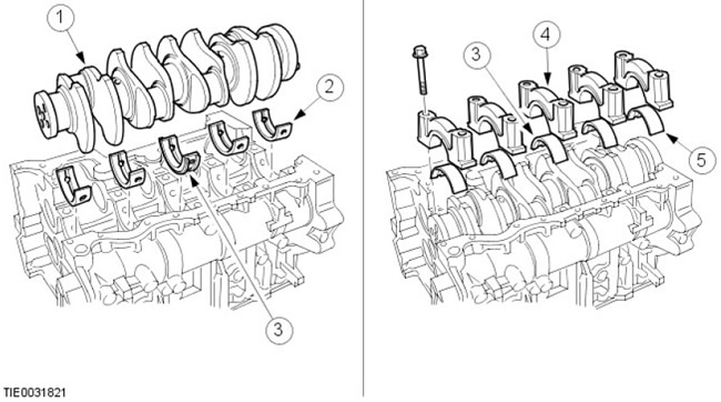
| Pos. | spare part no | Name |
| 1 | - | Crankshaft |
| 2 | - | Upper main bearing |
| 3 | - | Upper main bearing (No. 3 - thrust bearing) |
| 4 | - | bearing cap |
| 5 | - | Lower main bearing |
The crankshaft is made of forged steel. The main and connecting rod journals are hardened by high-frequency hardening. The crankshaft is mounted in 5 main bearings with a 2-layer housing.
The crankshaft drive pulley is fixed relative to the shaft not with a key, but with only one bolt.
The main bearing caps are doubled and fastened with bolts installed in two planes. This helps to increase the strength and rigidity of the cylinder block.
Selectively selected aluminum-tin split liners are used as main bearings. An oil groove at the top of each bearing conveys oil to the crankshaft to lubricate the connecting rod bearings. The upper and lower bushings of the third bearing have built-in thrust washers that limit the axial play of the crankshaft.
The arrow on the bearing caps must point towards the front of the engine, the markings are as follows:
| bearing cap | Identification |
| 1 | F (anterior) |
| 2 | 2 |
| 3 | 3 |
| 4 | 4 |
| 5 | R (rear) |
The front and rear crankshaft oil seals are pressed into holders.
Ladder frame and sump
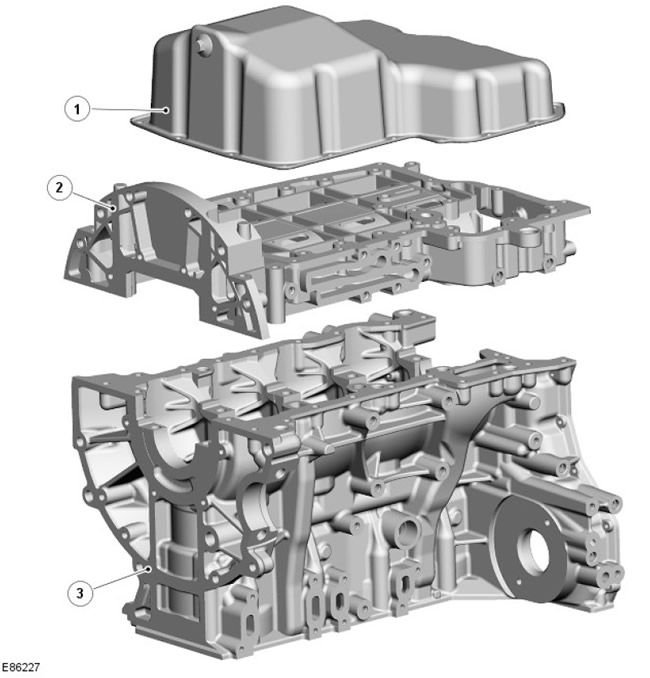
| Pos. | spare part no | Name |
| 1 | - | Oil pan |
| 2 | - | Stair construction |
| 3 | - | Cylinder block |
Aluminum alloy ladder frame mounted on cylinder block to improve engine rigidity and reduce noise, vibration and harshness (NVH). The structure is made of high pressure die-cast aluminum and includes an oil slinger to reduce foaming and oil splashing.
The side clearance between the ladder frame and the cylinder block must be adjusted using a special tool. The back gap is adjustable with a suitable ruler (for more information, see the manual for service stations).
The ladder frame is attached to the cylinder block with 22 bolts. The pressed steel sump is attached to the ladder frame with 16 bolts. The sump drain plug is located on the back of the sump, and the oil level/temperature sensor is located on the right side of the ladder frame, behind the turbocharger drain pipe.
The oil pump is bolted to the underside of the ladder frame at the front left side of the ladder frame and is driven from the crankshaft sprocket by a chain drive (for more information, see the section on the lubrication system).
A reusable gasket is provided to seal the joint between the oil pan and the ladder structure; a sealant is used to seal the joint between the oil pan and the ladder structure.
Oil filter and oil cooler assembly
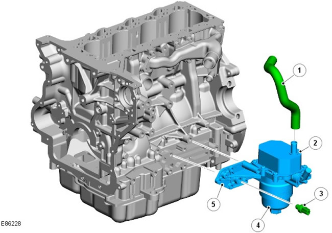
| Pos. | spare part no | Name |
| 1 | - | Hose - coolant manifold to oil cooler |
| 2 | - | Oil radiator |
| 3 | - | Oil pressure sensor |
| 4 | - | Oil filter |
| 5 | - | base plate |
The oil filter and oil cooler assembly is fixed to the left side of the ladder frame with 6 bolts. The oil pressure sensor passes through the base plate of the oil filter and oil cooler assembly to the ladder frame (for more information, see the section on the lubrication system).
Comments on this article