Contents: Crankshaft ⇩ Main bearings ⇩ Staircase construction ⇩ Oil pan ⇩ Oil temperature sensor ⇩ Rear Oil Seal Holder ⇩ Double flywheel ⇩
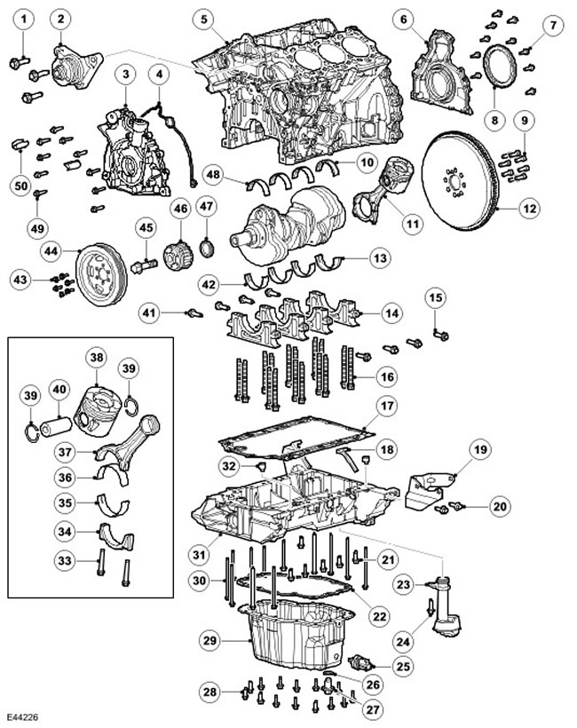
| Item name | Spare part catalog number | Description |
| 1 | - | Bolts, 3 pcs. |
| 2 | - | Fan drive bracket |
| 3 | - | Oil pump |
| 4 | - | Sealing |
| 5 | - | Cylinder block |
| 6 | - | Rear Oil Seal Holder |
| 7 | - | Bolts, 10 pcs. |
| 8 | - | Crankshaft Position Sensor Target |
| 9 | - | Bolts, 8 pcs. |
| 10 | - | Main thrust bearing, upper |
| 11 | - | Piston with connecting rod assembly |
| 12 | - | Flywheel |
| 13 | - | Main thrust bearing, lower |
| 14 | - | Main bearing caps, 4 pcs. |
| 15 | - | Cross bolts, 4 pcs. |
| 16 | - | Main bearing cap bolts, 16 pcs. |
| 17 | - | Pad |
| 18 | - | Sealing |
| 19 | - | Bracket |
| 20 | - | Bolts, 2 pcs. |
| 21 | - | Bolts, 6 pcs. |
| 22 | - | Pad |
| 23 | - | Oil pickup tube |
| 24 | - | Bolt |
| 25 | - | Oil temperature sensor |
| 26 | - | Sealing |
| 27 | - | Drain plug |
| 28 | - | Bolts, 14 pcs. |
| 29 | - | Oil pan assembly |
| 30 | - | Bolts, 12 pcs. |
| 31 | - | Staircase construction |
| 32 | - | Pin |
| 33 | - | Bolts, 2 pcs. |
| 34 | - | Connecting rod cap |
| 35 | - | Connecting rod bearing cap |
| 36 | - | Connecting rod bearing |
| 37 | - | Connecting rod |
| 38 | - | Piston |
| 39 | - | Piston pin holder |
| 40 | - | Piston pin |
| 41 | - | Cross bolts, 4 pcs. |
| 42 | - | Lower main bearings |
| 43 | - | Bolts, 5 pcs. |
| 44 | - | Crankshaft damper clutch pulley |
| 45 | - | Bolt |
| 46 | - | Crankshaft drive pulley |
| 47 | - | Front crankshaft oil seal |
| 48 | - | Upper main bearings |
| 49 | - | Bolts, 10 pcs. |
| 50 | - | Sealing |
Crankshaft
The crankshaft is made from forged steel with a rolled fillet and induction hardened journals, fitted to four bearings with clamping double-layer liners.
The main bearing caps are double-bolted with transverse bolts, which provides additional strength and rigidity to the cylinder block.
The crankshaft drive pulley is attached to the shaft not with a key, but with one bolt.
NOTE: Under no circumstances should the crankshaft pulley be tightened or loosened while the timing belt is installed.
NOTE: Do not attempt to remove the crankshaft pulley unless you have the proper crankshaft locking tool.
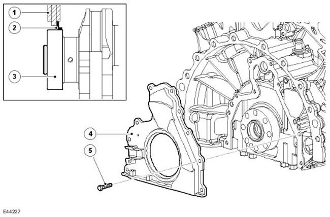
| Item name | Spare part catalog number | Description |
| 1 | - | Frame |
| 2 | - | Sealing |
| 3 | - | Crankshaft |
| 4 | - | Rear Oil Seal Holder |
| 5 | - | Bolt |
The rear crankshaft oil seal is pressed into the rear oil seal holder. The rear oil seal holder also houses the CKP sensor.
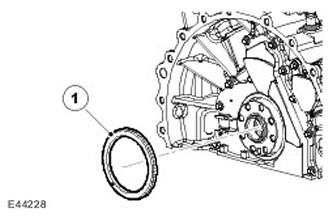
| Item name | Spare part catalog number | Description |
| 1 | - | CKP sensor target |
The target is located at the rear of the crankshaft. The target is pressed onto the crankshaft using a special tool, which also ensures precise target placement for correct crankshaft position and valve timing. The target consists of 60 magnets minus 2 for determining the crankshaft position by the ECM and synchronization. The magnets on the target are not visible, so the target can only be positioned correctly using a special tool.
The CKP sensor air gap is 0.4-0.5 mm and does not require adjustment. The sensor is bolted to the rear oil seal holder, and the tolerances on the holder and sensor provide the required air gap.
NOTE: If the target is removed for any reason, a new target must be installed. Do not reuse the old target.
Main bearings
Selected aluminum/tin split bearings are used as main bearings. The oil groove in the upper half of each bearing supplies engine oil to the crankshaft to lubricate the connecting rod bearings. Thrust washers are mounted in the upper and lower shells of the fourth bearing, limiting the axial play of the crankshaft.
Staircase construction
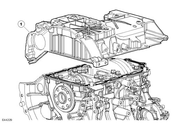
| Item name | Spare part catalog number | Description |
| 1 | - | Staircase construction |
The ladder-type design, mounted on the cylinder block, provides increased engine rigidity and reduced noise, vibration and low-frequency vibration (NVH). The structure is die-cast aluminum and includes an oil deflector to reduce foaming and oil splashing.
The ladder frame is secured to the cylinder block with 2 pins, 2 spacer centering pins and 18 mounting bolts, using three bolt lengths:
- M6 x 20, 6 pcs.
- M8 x 75, 4 pcs.
- M6 x 105, 8 pcs.
Iron inserts cast into the ladder-type main bearing supports ensure minimal bearing clearance change due to thermal expansion.
The joint between the ladder structure and the cylinder block is sealed with a gasket.
The casting on the left side of the structure provides a channel for the oil dipstick tube.
At the front of the structure is an oil intake pipe with an internal mesh filter, which provides oil to the crankshaft-driven oil pump.
Oil pan
The oil pan is made from stamped steel and is secured to the aluminum alloy ladder frame with 14 M6 x 16 bolts. The engine drain plug and oil temperature sensor are located in the left rear corner of the oil pan.
The material was taken from the specified website (LRMAN.ru)
A reusable gasket is provided to seal the joint between the oil pan and the ladder structure.; a sealant is used to seal the joint between the oil pan and the ladder structure.
Oil temperature sensor
The engine oil temperature sensor is mounted in the left rear corner of the oil pan. This sensor provides the ECM and instrument cluster with engine oil temperature data.
The sensor circuit includes an internal voltage divider circuit that includes a negative temperature coefficient (NTC) thermistor. As the engine oil temperature increases, the sensor resistance decreases and vice versa. The sensor output is a voltage change that occurs due to the increase in current flowing through the thermistor to ground in accordance with the change in oil temperature. For more information, refer to Electronic Engine Controls (303-14C Electronic Engine Controls - 2.7L Diesel).
Rear Oil Seal Holder
The rear crankshaft oil seal holder is secured with 10 bolts at the rear of the cylinder block via a rubber seal. The crankshaft position sensor is mounted in the holder.
Double flywheel
In vehicles with a manual transmission, a dual flywheel is attached to the crankshaft with 8 bolts. A key on the crankshaft flange ensures the correct position of the flywheel. A crown gear is mounted on the outer diameter surface of the flywheel. The crown gear is maintenance-free.
The dual flywheel design isolates the transmission from transient and torsional vibrations generated by the engine. For more information, visit Clutch (308-01 Clutch - 2.7L Diesel).
Comments on this article