


Contents: Cylinder heads ⇩ Camshaft covers ⇩ Cylinder head gasket ⇩ Gasket table ⇩ Camshafts ⇩ Timing ⇩ Inlet and outlet valves ⇩ Vacuum pump ⇩ Fuel injectors ⇩ Water outlet assembly ⇩
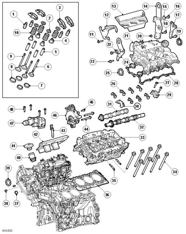
| Item name | Spare part catalog number | Description |
| 1 | - | Hydraulic valve clearance compensators |
| 2 | - | Valve spring plates |
| 3 | - | Roller Levers |
| 4 | - | Valve stem seals |
| 5 | - | Valve guide bushings |
| 6 | - | Exhaust valves |
| 7 | - | Intake valves |
| 8 | - | Exhaust valve seats |
| 9 | - | Intake valve seats |
| 10 | - | Valve springs |
| 11 | - | Bolt |
| 12 | - | Bracket |
| 13 | - | Lid |
| 14 | - | Mounting eye |
| 15 | - | Washer |
| 16 | - | Bolt |
| 17 | - | Bracket |
| 18 | - | Bolt |
| 19 | - | Sealing |
| 20 | - | Lid |
| 21 | - | Intake manifold cover assembly |
| 22 | - | Washer |
| 23 | - | Bolt |
| 24 | - | Mounting eye |
| 25 | - | Sealing |
| 26 | - | Camshaft Bearing Caps |
| 27 | - | Bolts |
| 28 | - | Pad |
| 29 | - | Seal housing and camshaft bearing cap |
| 30 | - | Seal housing and camshaft bearing cap |
| 31 | - | Intake camshaft |
| 32 | - | Exhaust camshaft |
| 33 | - | Left cylinder head |
| 34 | - | Cylinder head bolts |
| 35 | - | Exhaust manifold studs |
| 36 | - | Left cylinder head gasket |
| 37 | - | Plug |
| 38 | - | Plug |
| 39 | - | Sealing |
| 40 | - | Oil filler tube |
| 41 | - | Oil filler cap |
| 42 | - | Lid |
| 43 | - | Nozzles |
| 44 | - | Bolts |
| 45 | - | Bolt |
| 46 | - | Vacuum pump |
| 47 | - | Water outlet assembly |
| 48 | - | Bolts |
Cylinder heads
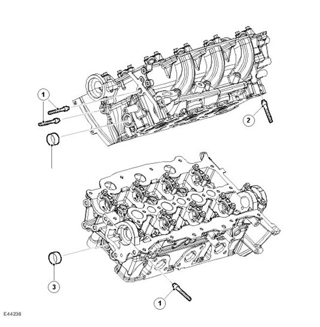
The cylinder heads of each row, cast from aluminum using a chill casting, are not interchangeable. Each cylinder head is fastened to the cylinder block by 8 deep-set bolts to reduce deformation. The cylinder head mounting bolts are located under the camshafts: 4 under the inlet camshaft and 4 under the outlet camshaft. 2 hollow pins ensure the alignment of each cylinder head with the cylinder block.
NOTE: When the camshafts are installed, the head and cylinder mounting bolts are not accessible.
NOTE: The cylinder head must not be subjected to any additional machining.
There are 4 channels in the cylinder head. (2 outlets and 2 inlets), formed at the locations of each cylinder. One of the intake channels is spiral-shaped and acts as a swirl channel, the other is located on the side, creating a tangential flow, and acts as a charging channel.
The six fuel injection injectors are centrally located, one injector above each cylinder, with each injector secured to the cylinder head by a clamp and 2 M6 x 35 bolts. For more information, refer to Electronic Engine Controls (303-14C Electronic Engine Controls - 2.7L Diesel). For more information, see Fuel Charging and Controls (303-04C Fuel Charging and Controls - 2.7L Diesel).
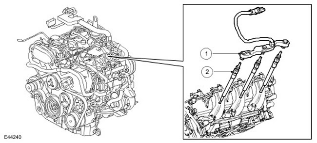
| Item name | Spare part catalog number | Description |
| 1 | - | Wiring harness connector |
| 2 | - | Glow plugs |
The glow plugs are located centrally on the intake side of the cylinder head, between the 2 intake ports of each cylinder. For more information, refer to Electronic Engine Controls (303-14C Electronic Engine Controls - 2.7L Diesel).
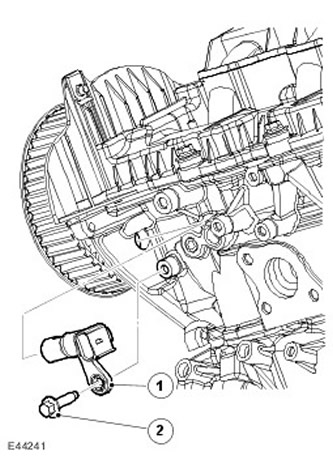
| Item name | Spare part catalog number | Description |
| 1 | - | Camshaft Position (CMP) Sensors |
The camshaft position sensor is located in a flange bore on the left front side of the left cylinder head. The left cylinder head exhaust camshaft sprocket (gear) has a target that the sensor uses to determine the position of the shaft. For more information, refer to Electronic Engine Controls (303-14C Electronic Engine Controls - 2.7L Diesel)
The engine mounting lugs are bolted to the cylinder head: two at the rear (one for each head) and one in front.
Camshaft covers
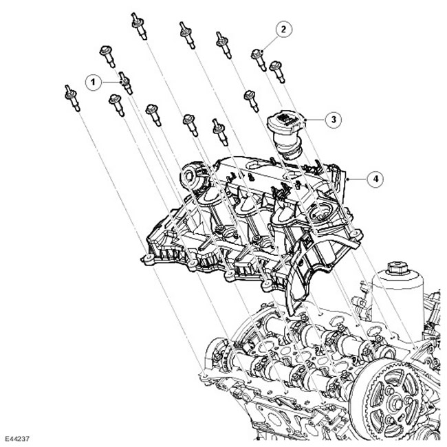
| Item name | Spare part catalog number | Description |
| 1 | - | Threaded stud M6 x 40, 6 pcs. |
| 2 | - | Bolt M6 x 40, 7 pcs. |
| 3 | - | Oil filler hole |
| 4 | - | Right cylinder bank camshaft cover assembly |
Camshaft covers are made of a composite material based on vinyl ether. The camshaft cover of the right row of cylinders has an opening for a full-load breather and an oil filler neck. The camshaft cover of the left row of cylinders has an opening for a partial load breather. For more information, refer to Engine Emission Control (303-08C Engine Emission Control - 2.7L Diesel).
The joints between the camshaft covers and the cylinder heads are sealed with recessed silicone rubber gaskets. Together with the spacer bushings and seals on the fasteners on the camshaft cover, they also prevent the covers from coming into direct contact with the cylinder heads, thereby reducing noise levels.
Cylinder head gasket
Cylinder head gaskets are three-layer steel gaskets. There are 5 gasket sizes available, each with a different thickness. The choice of the required size depends on the maximum piston protrusion. The gasket thickness is determined by the number of teeth cut into the front part of the gasket.
Gasket table
| Piston protrusion (mm) | Gasket thickness (mm) | Identification data |
| 0,541 - 0,590 | 1,12 | 1 |
| 0,591 - 0,640 | 1,17 | 2 |
| 0,641 - 0,690 | 1,22 | 3 |
| 0,691 - 0,740 | 1,27 | 4 |
| 0,741 - 0,790 | 1,32 | 5 |
To calculate the required cylinder head gasket thickness, measure each piston in two places and then calculate the average to determine the piston protrusion. The larger of the three values will indicate which size gasket to use for that cylinder head.
NOTE: The difference between the minimum and maximum piston protrusions in any row must not exceed 0.1 mm. It is permissible to use gaskets of different sizes for the cylinder heads of the right and left rows.
Camshafts
The camshafts are of hollow tubular steel construction, and the cams are manufactured using powder metallurgy pressing technology. Each camshaft is secured by aluminum alloy caps: five caps are used for the exhaust camshafts and four caps for the intake camshafts. On the top side of the cap, each cylinder bank is marked: A to I for the intake camshaft and R to Z for the exhaust camshaft.
The left bank exhaust camshaft is machined to accept the rear camshaft sprocket. The rear camshaft sprocket drives the high-pressure fuel pump, which is located centrally at the rear of the V-bank, via a short-tooth belt and tensioner.
The right cylinder head exhaust camshaft is machined at the rear to accommodate the vacuum pump drive.
NOTE: The camshaft sprockets also form thrust surfaces, limiting the shaft end play. The end play of a new shaft is 0.065 mm to 0.185 mm. If, during repair, the shaft end play is found to be outside the specified limits, the camshaft(s) or cylinder head(s) may need to be replaced.
Timing
| Valve | Position |
| Opening the intake valve | 8.5° before TDC |
| Closing the intake valve | 35.5° after BDC |
| Opening the exhaust valve | 64° before BDC |
| Closing the exhaust valve | 12° after TDC |
Inlet and outlet valves
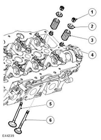
| Item name | Spare part catalog number | Description |
| 1 | - | Valve spring bushings |
| 2 | - | Valve spring plate |
| 3 | - | Valve spring |
| 4 | - | Valve stem seal |
| 5 | - | Inlet valve |
| 6 | - | Exhaust valve |
Each cylinder head has 2 overhead camshafts, driving 4 valves per cylinder via steel roller levers with hydraulic lash adjusters.
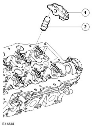
| Item name | Spare part catalog number | Description |
| 1 | - | Roller lever |
| 2 | - | Hydraulic clearance compensator |
The lightweight valve mechanism ensures low fuel consumption and low noise levels. The valve head diameters are 31 mm (1.220 inches) at the inlet and 35 mm (1.378 inches) on the outlet. The stems of all valves have a diameter of 5 mm (0.197 inches), and are supported by guide bushings and seats made of metal powders by a sintering process. In both the intake and exhaust valves, single valve springs are retained by bushings, valve plates and spring seats. Valve stem seals are integrated into the spring seats.
Vacuum pump
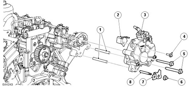
| Item name | Spare part catalog number | Description |
| 1 | - | Positioning pins |
| 2 | - | Bracket |
| 3 | - | Vacuum pump |
| 4 | - | Bolt |
| 5 | - | Bolts |
| 6 | - | Screw |
| 7 | - | Bracket (gearbox breather hose) |
| 8 | - | Hairpin |
The vacuum pump is located at the rear of the right-hand cylinder head and is driven by the exhaust camshaft.
Fuel injectors
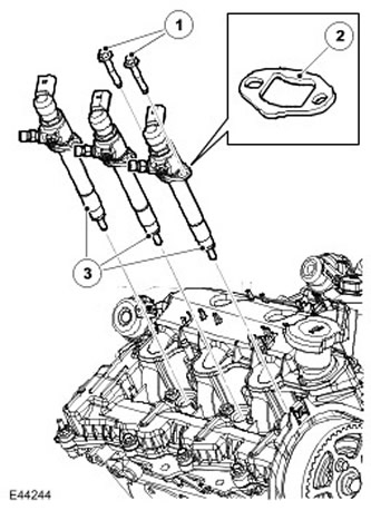
| Item name | Spare part catalog number | Description |
| 1 | - | Bolt, 2 pcs. for each injector |
| 2 | - | Clamp |
| 3 | - | Nozzles |
Fuel injectors inject the required amount of fuel into the combustion chambers in accordance with the current engine load. In each working cycle, fuel injection is carried out in two stages: first, a noise-reducing preliminary injection is performed, and then the main injection.
The fuel rails are equipped with 6 fuel injectors with side fuel supply and piezoelectric control. The moment of injection start and the amount of fuel injected are regulated directly by the ECM. The places of attachment of the injectors to the pipeline are sealed with 2 ring seals. For more information, refer to Electronic Engine Controls (303-14C Electronic Engine Controls - 2.7L Diesel). For more information, see Fuel Charging and Controls (303-04C Fuel Charging and Controls - 2.7L Diesel).
Water outlet assembly
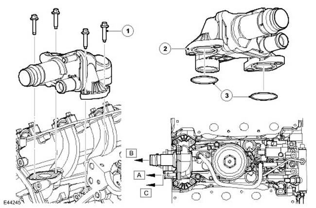
| Item name | Spare part catalog number | Description |
| 1 | - | Bolt, 4 pcs. |
| 2 | - | Water outlet assembly |
| 3 | - | Seals |
| A | - | Water outlet housing assembly, EGR system outlet |
| B | - | Water outlet housing assembly, radiator outlet |
| C | - | Water outlet body assembly, outlet valve |
The water outlet assembly connects the cooling passages of the cylinder block to the cooling passages of the right and left cylinder heads and provides the outlet of coolant for the EGR system and its return.
Comments on this article