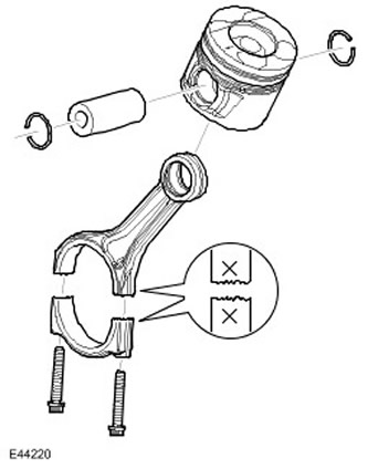
The connecting rods are made of steel by sintering and forging and have split bearing caps. The bearing caps are made by breaking the connecting rod along the horizontal axis of the bearing. In addition to simplifying the manufacture, during reassembly the fracture surfaces interlock, forming a seamless strong connection. The cylinder position is marked on the mating surfaces to identify the correspondence of the connecting rods and the bearing cap. Aluminum/tin split plain bearings are used as selected connecting rod bearings. The connecting rod bearing has a special coating, which allows the bearing to withstand a greater load and increases its service life.
NOTE: Connecting rods are not select.
Installing connecting rods

| Item name | Spare part catalog number | Description |
| 1 | - | Piston with connecting rod assembly, cylinders 4-6 |
| 2 | - | Piston with connecting rod assembly, cylinders 1-3 |
| 3 | - | Bolts |
| 4 | - | Connecting rod bearing cap |
| 5 | - | Lower connecting rod bearing |
When installing the connecting rod, make sure that its back side faces the center of the V-shaped cylinders.
The pistons are made of aluminum alloy and are equipped with three rings. The piston head has a clearly defined recess. This creates a combustion chamber that promotes swirl and turbulent movement, which is necessary for complete combustion of the fuel-air mixture and reduced emissions. In addition, the piston skirt has a molybdenum coating that prevents scuffing of the cylinder bore and piston surfaces.
The piston head has a double wave gallery that improves piston cooling. Oil is supplied to the pistons through nozzles located in the cylinder block oil line. These nozzles provide optimal piston cooling to reduce the temperature that increases during the combustion process.
Each piston is mounted on a piston pin, which is installed in an aluminum/tin connecting rod bushing.
Installing pistons

When installing the pistons, make sure that all arrows and piston heads are directed towards the front side of the engine, and the pistons themselves are located in the corresponding rows of cylinders, i.e. in cylinders 1, 2, 3 or 4, 5, 6.
NOTE: All pistons in all engines are the same size and part numbers.
The top piston ring is tapered and tapers towards the piston crown. All rings marked 'top' must be installed with the 'top' marking facing upwards. All rings must be evenly spaced around the piston before installation. The gap of the double bevel oil control ring must be on the side opposite the spiral seam.
The text of the article was taken from the website www.lrman.ru
Comments on this article