car logo Ford
car logo Volkswagen
car logo BMW
car logo Opel
car logo Audi
car logo Toyota
car logo Peugeot
English Русский
Български
Беларускі
Український
Српски
Hrvatski
Română
Polski
Slovenský
Magyar


Main
Freelander
Discovery
Range Rover
Defender
Contacts
Articles

A connecting lever connected to the sector steering arm lever (Defender 2007+)

 
  • Main
  • Defender
  • Defender 2007+
  • Chassis
  • Steering
  • A connecting lever connected to the sector steering arm lever
 
        0  
Contents: Removal ⇩ Installation ⇩

Removal


1. Place the vehicle on a level, horizontal surface and place wheel chocks under the rear wheels.

2. Move the wheels to the straight ahead position.

3. Raise the vehicle and place secure supports underneath it or use a lift.

4. Remove the front wheel.

5. Disconnect the steering shock absorber from the bracket securing the longitudinal steering rod to the sector shaft lever.

6. Remove the cotter pin and unscrew the crown nut securing the ball joint of the longitudinal steering rod of the sector shaft lever to the steering knuckle lever.

7. Disconnect the ball joints of the longitudinal steering rod of the sector shaft lever using the LRT-57-018 tool.

8. Remove the longitudinal steering rod of the sector shaft lever.

9. Loosen the clamp bolts.

10. Unscrew the ball joints and remove the sector shaft lever from the longitudinal steering rod.
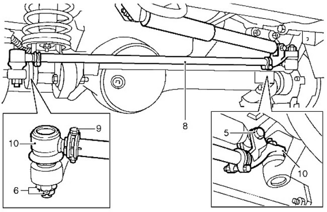
10. Unscrew the ball joints and remove the sector shaft lever from the longitudinal steering rod.


Installation


1. Clean the internal thread of the sector shaft lever longitudinal steering rod.

2. Install new ends onto the sector shaft lever longitudinal steering rod and loosely screw in the clamp bolts.


3. Adjust the installation size of the ball joints on the longitudinal steering rod of the sector shaft lever to 28.5 mm.

4. Adjust the ball joint centers to the nominal length of 924 mm. This length is adjusted during installation.
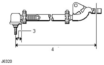
4. Adjust the ball joint centers to the nominal length of 924 mm. This length is adjusted during…


5. Center the steering gear.

For more information, refer to the chapter: Steering Gear Centering (211-00 Steering System - General Information, General Procedures).

6. If necessary, adjust the position of the steering wheel.

7.
CAUTION: A damaged or bent sector shaft arm trailing arm must be replaced. DO NOT attempt to repair.


Connect the longitudinal steering rod of the sector shaft lever to the steering knuckles and tighten the nuts to 40 Nm. Install new cotter pins.

8. Make sure that the steering wheel has full travel between the limit positions.

For more information, refer to the chapter: Adjusting the steering lock system (211-00 Steering System - General Information, General Procedures).

Adjust the length of the longitudinal steering rod of the sector shaft lever as required.

9. Rotate the ball joints in the direction shown so that both pins are in the same plane.
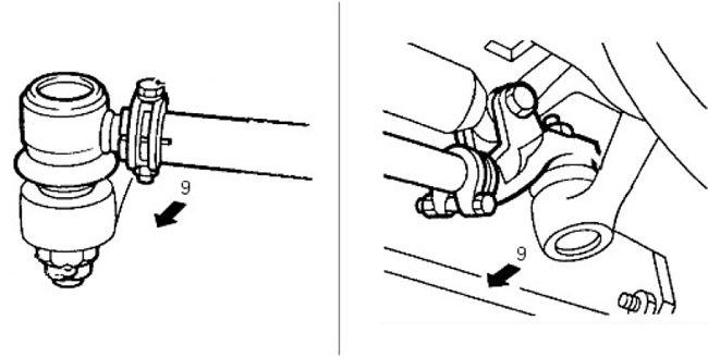


9. Rotate the ball joints in the direction shown so that both pins are in the same plane.


10. Tighten the clamp bolts to 14 Nm.

11. Install the wheel and remove the supports from under the vehicle or remove the vehicle from the lift.

12. Road test the vehicle.

13.
CAUTION: To correct steering wheel offsets greater than ±5°, remove and reinstall the steering wheel.


If the wheels are pointing straight ahead and the steering wheel offset is 0° ±5° in either direction, correct the position by adjusting the length of the sector shaft arm trailing arm.


This article is available at russian, bulgarian, belarusian, ukrainian, serbian, croatian, romanian, polish, slovak, hungarian
Article review: Saveliy Ushakov


Previous articles
Steering Specifications
Filling and bleeding the power steering system
Power steering system flush
Steering adjustment
Adjusting the steering lock system
Description and operating principle of the steering control
Steering diagnostics and checks
Steering gear centering

Current article
A connecting lever connected to the sector steering arm lever

Next article
Steering knuckle


Similar articles from Land Rover repair manuals:
• Automatic transmission selector lever Freelander 2 (2006-2014)
• Parking brake lever assembly Freelander 1 (1997-2006)
• Wheel alignment lever Discovery 3 (2004-2009)
• Adjustments — accelerator cable (fuel injection pump lever) Discovery 1 (1989-1998)
• Gear selector lever Range Rover 3 (2001-2012)

Comments on this article


No comments yet


How much will 32 + 46 =


Defender 2007+ 
  • General information
  • Maintenance
  • Identification codes
  • Power unit
  • Diesel engine ID4 2.4L
  • Engine inspection
  • Engine cooling
  • Fuel supply
  • Fuel tank
  • Exhaust system
  • Accessory drive
  • Air filtration
  • Electronic parts
  • Mechanical gearbox
  • Transfer case
  • Clutch
  • Chassis
  • Car suspension
  • Wheels and tires
  • Steering
  • Steering column
  • Brake system
  • Front drive axle
  • Rear drive axle
  • Cardan shaft
  • Body and coating
  • Interior trim
  • Instrument panel and console
  • Exterior finish
  • Lockable body parts
  • Handles, locks, latches
  • Glass, frames and mechanisms
  • Windshield wipers and washers
  • Seats
  • Electrical equipment
  • Battery
  • Generator and regulator
  • Lighting and headlights
  • Winch
  • Heating and ventilation
  • Instrument panel
  • Other electronics


LRman.ru © 2013-2026 | Mobile version | Free Lander | Discovery | Range Rover | Defender | Contacts | | Sitemap |
Car repair and service instructions Land Rover: Freelander, Discovery, Range Rover, Defender
We use cookies to make pages load faster and provide a more user-friendly experience 🍪