Power steering system
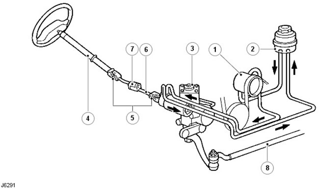
| Pos. | spare part no | Name |
| 1. | - | Hydraulic pump |
| 2. | - | Liquid tank |
| 3. | - | Steering gear housing |
| 4. | - | Upper section of column |
| 5. | - | Cardan joints |
| 6. | - | lower shaft |
| 7. | - | Crimp connection |
| 8. | - | Longitudinal tie rod |
Elements of the crankcase of the power steering mechanism
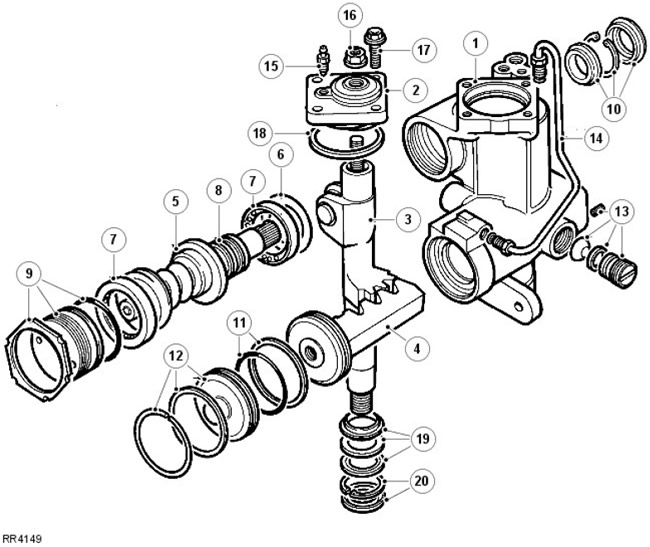
| Pos. | spare part no | Name |
| 1. | - | Crankcase with sector shaft bearings |
| 2. | - | Cover with bearing |
| 3. | - | sector shaft |
| 4. | - | Hydraulic piston/ rack |
| 5. | - | Worm / valve assembly with torsion bar |
| 6. | - | Shims for worm/valve centering |
| 7. | - | ball bearing |
| 8. | - | Teflon seals for spool |
| 9. | - | Bearing adjuster, locknut and seal |
| 10. | - | Worm shaft seal, circlip and dirt trap |
| 11. | - | Teflon and rubber piston seal |
| 12. | - | End cap seal and circlip |
| 13. | - | Piston/rack adjusters |
| 14. | - | Hydraulic pipeline |
| 15. | - | Air outlet |
| 16. | - | Sector shaft adjustment locknut with seal |
| 17. | - | Cover bolts |
| 18. | - | Cover seal |
| 19. | - | Seal, washer and backup seal |
| 20. | - | Retaining ring and dust cover |
There is a crimp connection on the lower shaft of the steering system. It is designed to collapse on impact. The misalignment of the upper section of the steering column and the steering gear housing and the presence of two universal joints are also designed to prevent the column from moving towards the driver in a frontal collision.
The steering gear housing is located behind the first cross member of the chassis and is connected by the steering knuckles of the wheels with the help of a longitudinal steering rod and a transverse steering rod. The hydraulic shock absorber absorbs steering shocks caused by wheel deflection when driving on uneven road surfaces.
Power steering system
The power steering system includes a hydraulic pump that is belt driven by the engine and receives fluid from a reservoir that also acts as a coolant.
The steering gear housing contains a self-centering spool valve, which is part of a worm/valve and a hydraulic piston/rack to facilitate mechanical operation. A spool valve, which is actuated by movement of the steering wheel, directs fluid pressure to the appropriate side of the hydraulic piston/rack to provide boost.
Spool valve operation
Spool valve in neutral position
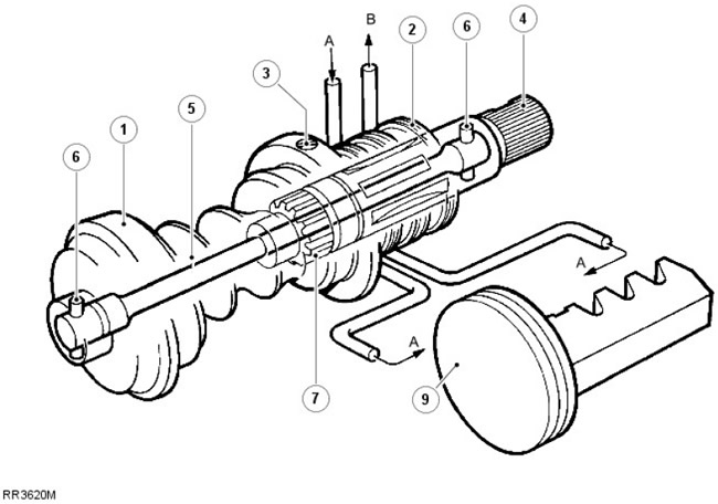
Spool valve assembly includes worm (1), spool (2), input shaft (4) and torsion (5).
The spool is held inside the worm by an adjusting screw (3). Valve ports are located on its inner wall. The input shaft is connected to the steering wheel by means of the steering shaft and steering column and has valve ports on the outer diameter that are aligned with the ports in the spool.
When there is no request for reinforcement, the torsion bar, which is attached to the worm and input shaft by means of pins (6), located at each end holds the valve ports in a neutral position.
When there is no demand for boost, the torsion bar holds the valve ports of the input shaft and spool valve in a neutral position relative to each other, allowing equal pressure to be applied from the pump (A) to both sides of the piston/rack (9). Any excess fluid from the pump is returned to the reservoir via (B).
Spool valve offset
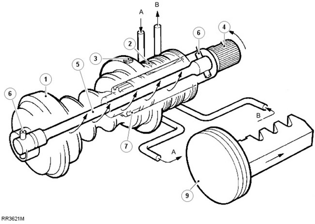
As the steering wheel and input shaft turn, the steering resistance transmitted to the worm causes the torsion bar to twist and the valve ports move to turn right or left. Offset valve ports direct all fluid pressure to only one side of the piston and allow Fluid B to move to the other side.
When maximum boost is requested, all of the excess fluid leaving the pump due to the high pump speed will circulate through the control valve located in the pump, causing the fluid and pump temperatures to rise rapidly.
CAUTION: To avoid elevated fluid temperatures that can damage oil seals, do not hold steering for more than 30 seconds in one minute.
Only after releasing the steering wheel and requesting boost will the torsion bar return the valve to neutral, allowing fluid to circulate through the reservoir where it cools.
In the unlikely event of a mechanical failure of the torsion bar, the coarse spline (7) between the input shaft and the worm allows the steering to remain operational to regain control of the vehicle.
Pump and control valve operation
No Gain Request
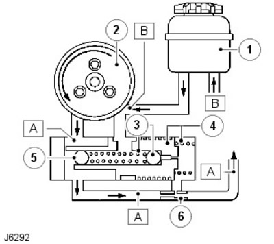
| Pos. | spare part no | Name |
| 1. | - | Tank |
| 2. | - | Pump |
| 3. | - | Pressure control ball valve and spring |
| 4. | - | Flow control valve and spring |
| 4. | - | Plug fitted with a press fit (ball bearing) |
| 5. | - | limiter |
The pump which is belt driven by the engine is an eccentric roller pump. It also contains a pressure regulator and a flow control valve. Pressure controlled by spring loaded ball valve (3), which is located inside the flow control valve piston (4).
When there is no demand for boost, the spool valve in the steering case acts as a relief valve, allowing the fluid to (A) flow freely through the steering gear housing and back to the reservoir and pump inlet (B).
When the steering wheel is turned, the spool valve effectively stops all fluid flow through the steering gear housing, thus causing an increase in pressure (A). This increase in pressure is sensed in the spring chamber of the flow control valve, where, at a given pressure, the relief valve opens (3), which allows the pressure to be released. The pressure drop in the spring chamber allows the flow control valve to move to the right, which in turn allows fluid to exit the pump (A), flow straight into the pump inlet (B).
Gain Request
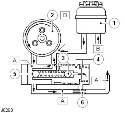
As soon as the steering wheel is released after making a turn, the system returns to the state shown in J6292 and the wheels return to the position "straight ahead" due to the geometry of the steering structure.
In the event of any failure of a hydraulic nature, steering capability will be maintained by mechanical elements in the steering gear housing, but the steering effort will be very high.
Comments on this article