Contents: Removal ⇩ Installation ⇩
Removal
1. Center the steering wheel.
- Fix the position, remove the key from the ignition switch.
2. Loosen the upper bolt of the lower steering column shaft.
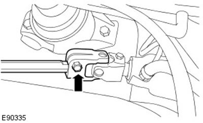
3. Disconnect the lower steering column shaft from the steering gear.
- Remove the lower bolt of the lower steering column shaft.
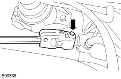
4.
Warnings:
- If power steering fluid comes into contact with the paintwork, the contaminated area should be washed immediately with cold water.
- Before disconnecting or removing components, clean the areas around hinges and connections. To prevent contamination of the system, plug all open connections.
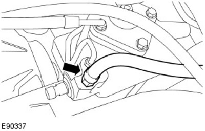
Disconnect the power steering (PAS) return hose from the steering gear.
- Place a suitable container to collect any spilled power steering fluid.
5.
Warnings:
- If power steering fluid comes into contact with the paintwork, the contaminated area should be washed immediately with cold water.
- Before disconnecting or removing components, clean the areas around hinges and connections. To prevent contamination of the system, plug all open connections.
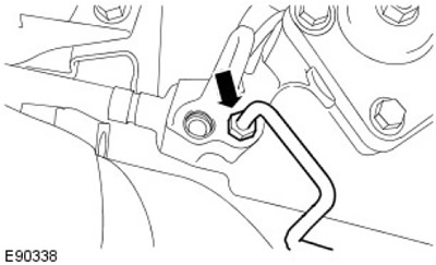
Disconnect the PAS supply line from the steering gear.
6.
WARNING: Never work on a vehicle supported only by a jack. Always support the vehicle with special stands.
Raise the vehicle and place supports underneath it.
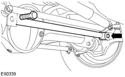
7. Remove the diagonal rod.
- Remove two bolts with two nuts of the diagonal rod.
- Discard the two diagonal tie rod nuts.
8.
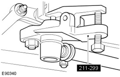
CAUTION: Do not damage the ball joint boot. Damage to the boot will result in premature failure of the ball joint.
Using a special tool, disconnect the longitudinal steering rod from the steering arm.
- Remove the cotter pin.
- Loosen the nut connecting the longitudinal steering rod to the steering arm.
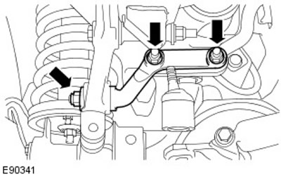
9. Remove the tie rod.
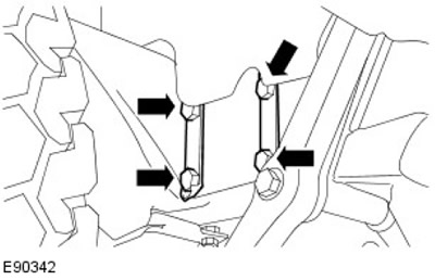
10. Remove the steering gear with assistance.
- Release the 2 lock washers.
- Remove and discard the 4 steering gear bolts.
- Remove and discard the 2 lock washers.
11.
NOTE: When installing a remanufactured steering gear, follow steps 12, 13 and 14.
Loosen the steering knuckle nut lock washer.
12. Unscrew and discard the steering knuckle nut.
- Discard the steering knuckle nut lock washer.
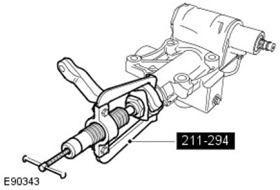
13. Using a special tool, remove the steering arm from the steering gear.
Installation
1. Clean the mating surfaces of the steering arm and steering gear.
2.
NOTE: Install a new nut and lock washer.
Install the steering arm onto the steering gear.
- Install the lock washer.
- Tighten, but do not fully tighten, the steering arm nut.
Data taken from the website www.LRman.ru
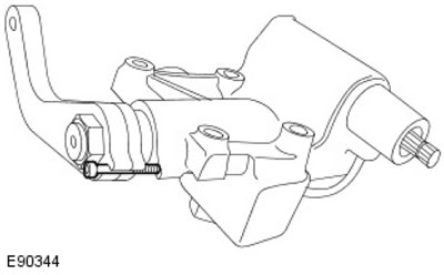
3. Install the centering bolt into the steering gear.
4. Secure the steering arm in a suitable vice.
5. Tighten the steering knuckle nut to 176 Nm.
6. Secure the steering arm nut with a lock washer.
7. Remove the steering gear from the vice.
8.
NOTE: Install new bolts and lock washers.
Install the steering gear with assistance.
- Install the lock washers.
- Insert and tighten the steering gear bolts to 65 Nm.
9. Secure the steering gear bolts with lock washers.
10. Install the tie rod and connect it to the steering gear.
- Install but do not tighten nuts and bolts.
11. Tighten the nut securing the transverse steering rod to the diagonal rod support bracket to 83 Nm.
12. Tighten the nuts and bolts securing the tie rod to the steering gear to 85 Nm.
13. Secure the longitudinal steering rod to the steering arm.
- Tighten the nut to 40 Nm.
- Install the cotter pin.
14.
NOTE: Install new nuts.
Install the diagonal tie rod.
- Tighten the nuts and bolts to 230 Nm.
15.
CAUTION: If power steering fluid comes into contact with the paintwork, immediately wash the contaminated area with cold water.
NOTE: Inspect the O-ring. If there is any sign of damage, install a new O-ring.
Connect the PAS supply line to the steering gear.
- Tighten to 20 Nm.
16.
CAUTION: If power steering fluid comes into contact with the paintwork, immediately wash the contaminated area with cold water.
NOTE: Inspect the O-ring. If there is any sign of damage, install a new O-ring.
Connect the PAS return hose to the steering gear.
- Tighten to 15 Nm.
17. Check alignment and install the lower steering column shaft onto the steering gear.
- Install and tighten the lower steering column lower shaft bolt to 22 Nm.
18. Tighten the upper bolt of the lower steering column shaft to 22 Nm.
19. Remove the centering bolt from the steering gear.
20. Fill the PAS system and bleed air from the system.
For more information, please refer to the chapter: Power Steering System Filling and Bleeding (211-00 Steering System - General Information, General Procedures).
Comments on this article